

Question: A block flow diagram which illustrates the process flow paths for an epoxyethane plant is illustrated in figure Q3. The bypass fraction, b, indicates the
A block flow diagram which illustrates the process flow paths for an epoxyethane plant is illustrated in figure Q3. The bypass fraction, b, indicates the amount of material in stream MF which is directed through stream BP e.g. if b = 0.35 then BP flowrate = 0.35 MF flowrate(for all components in MF). Hint: it is a simple junction balance.
The Fresh Feed (FF) consisting of ethene and air is combined with a recycle stream (RC) to form the Mixed Feed (MF). Process issues dictate that a proportion of the MF be diverted through a reactor Bypass (BP) pipe following which it is combined with the Reactor Product (RP) stream. Material which is not diverted through stream BP forms the Reactor Feed (RF). The separator feed (SF), which is formed from the confluence of the RP and the BP streams, is subsequently split into two streams by the ideal separator. The first, a Product stream (P), contains only water and epoxyethane. All of the water produced as a by-product in the reactor exits the process via stream P. A proportion, r, of the SP stream is diverted back through the process via a Recycle stream (RC), the remaining proportion (1- r) exiting via W.
The plant operates with an air fresh feed molar ratio = 12 (i.e. 12 mols of air to 1 mol of ethene), a reactor Conversion per pass, Cpp = 95%, a recycle fraction, r = 0.70 and a bypass fraction b = 0.35. 75% of the ethene converted per pass forms the primary product. The relevant reaction equations are the same as those provided in Q2 of this assignment.
C2H4 + 0.5 O2 = C2H4O [equation 1]
C2H4 + 3O2 = 2CO2 + 2H2O [equation 2]
Note, the equal sign is meant to be a right-pointing arrow.
Take 100 kmols/hour of ethene in the Fresh Feed as a basis and construct a complete material balance table for the process using Microsoft Excel. You must identify all components and quantities present in all process streams and it must be possible to readily identify the flowrate of each component in all pipe sections (units kmols/hour).
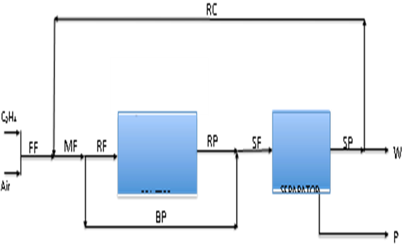 Figure Q3: BFD for the production facility described in question 3.
RC CHA 1 FF MF RF RP SE SP W Air CCARATOA BP P
Step by Step Solution
There are 3 Steps involved in it

Get step-by-step solutions from verified subject matter experts