

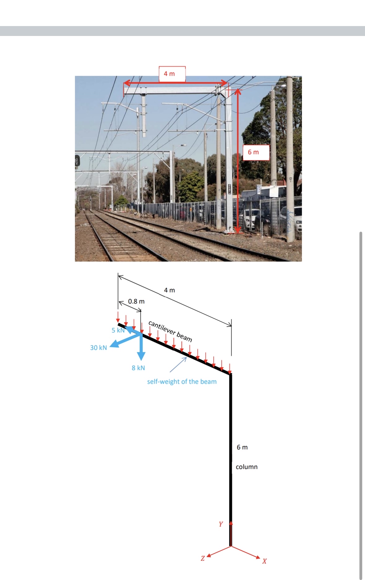
Question: A column and beam structure supporting electrified rail lines is shown in the picture below. It comprises a 6 m high column and a 4
A column and beam structure supporting electrified rail lines is shown in the picture below. It comprises a m high column and a m long beam centre line dimensions The structure is loaded by selfweight, wire static weight, electrical fittings weight, construction loading, wire tensions both parallel and perpendicular to the plane of the overhead wiring structure wind on the structure and wind on the wiring. We will simplify this and only consider: selfweight of the m long beam only you can use the centre line dimensions when calculating and applying this load ie ignore the halfwidth of the beam beyond the centreline at the intersection wire static weight of kN acting vertically as shown in the diagram wire tension of kN acting horizontally at right angles to the plane of the overhead wiring structure in the direction shown in the diagram wire tension of kN acting horizontally in the plane of the overhead wiring structure in the direction shown in the diagram The only loads and dimensions that you need to consider are those that are shown in the diagram. All loads are nominal values. No load factors are to be applied. Both the column and the beam are made from a hollow square steel box cross section The external dimensions of the cross section are mm x mm and the wall thickness is mm note none of these are the real dimensions Calculate the bending moment values in the column and the beam. Draw the bending moment diagram to scale noting all relevant values on the graphs. Calculate the torsion values in the column and the beam. Draw the torsion diagram to scale noting all relevant values on the graph. Calculate the maximum bending stress in the column at the foundation level. Calculate the shear stress, due to torsion only, in the column at the foundation level. Calculate the rotation of the column at the top of the column ie at m about the column axis. Calculate the horizontal deflection at the free end of the beam due to this rotation only All calculated values are to have the correct signs in accordance with the sign convention and the local axes directions shown on the diagram. All plots are to drawn in accordance with the convention. All diagrams are to be drawn as stick diagrams on the D axis system oriented as shown in the diagram. Show the global axes, and the local axes for each member.
Step by Step Solution
There are 3 Steps involved in it
1 Expert Approved Answer
Step: 1 Unlock

Question Has Been Solved by an Expert!
Get step-by-step solutions from verified subject matter experts
Step: 2 Unlock
Step: 3 Unlock