

Question: A copy of this wave interference pattern has been prepared for you. Please use the following document, Wave interference investigation, and use it to take


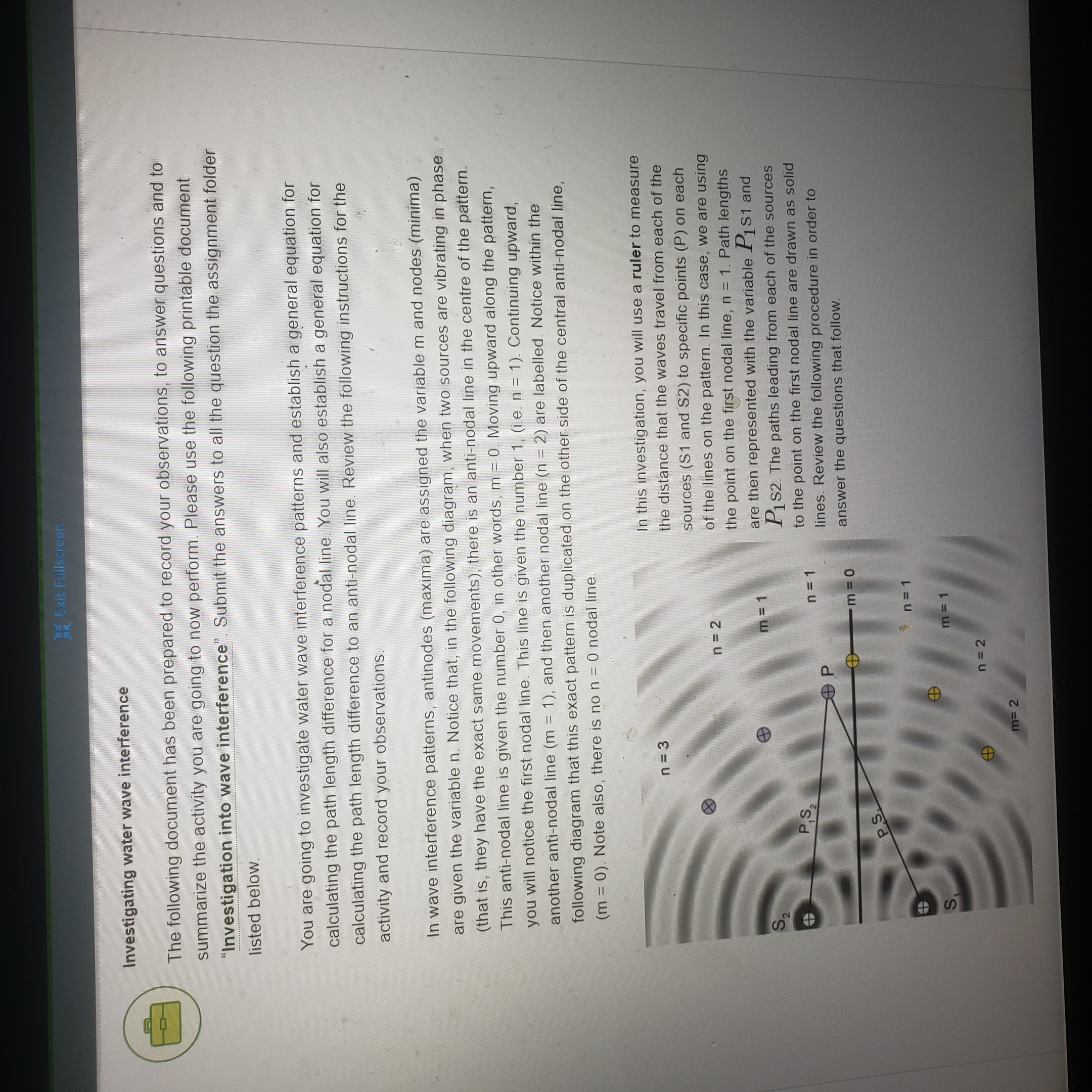
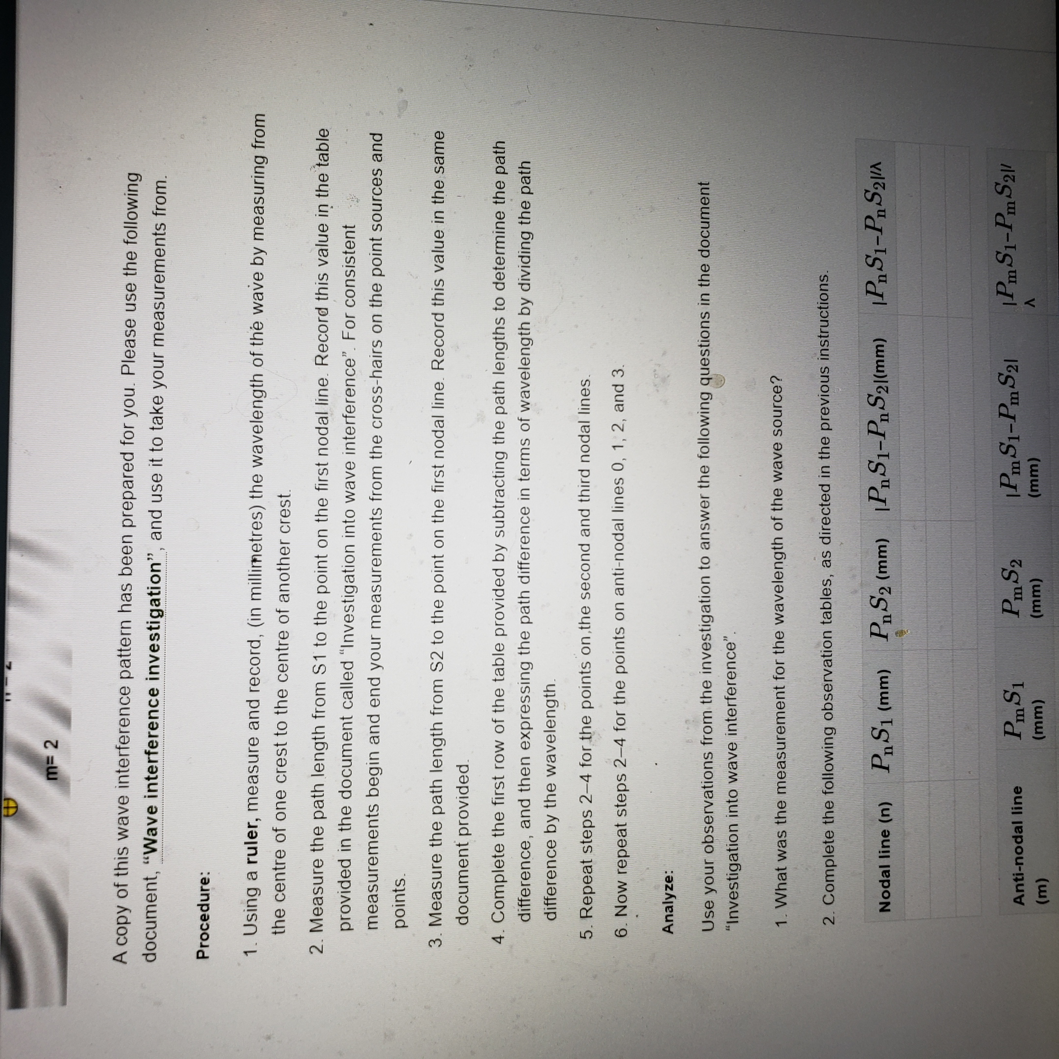
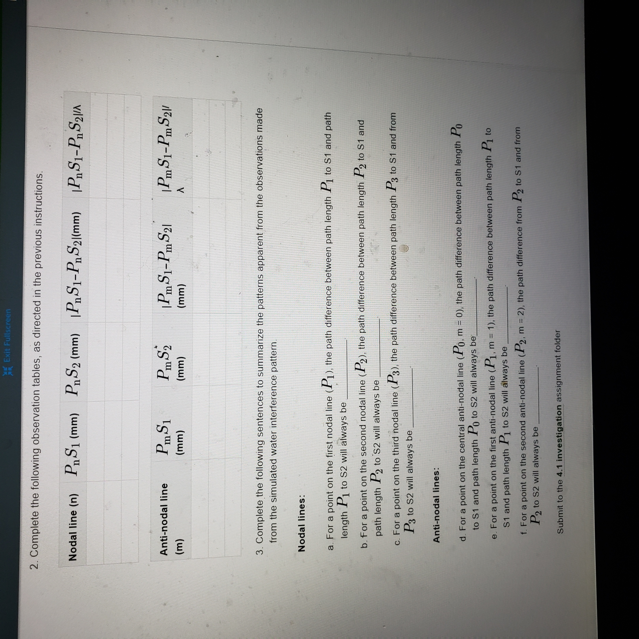

A copy of this wave interference pattern has been prepared for you. Please use the following document, "Wave interference investigation", and use it to take your measurements from. Procedure: 1. Using a ruler, measure and record, (in millimetres) the wavelength of the wave by measuring from the centre of one crest to the centre of another crest. 2. Measure the path length from $1 to the point on the first nodal line. Record this value in the table provided in the document called "Investigation into wave interference". For consistent measurements begin and end your measurements from the cross-hairs on the point sources and points. 3. Measure the path length from $2 to the point on the first nodal line. Record this value in the same document provided. 4. Complete the first row of the table provided by subtracting the path lengths to determine the path difference, and then expressing the path difference in terms of wavelength by dividing the path difference by the wavelength. 5. Repeat steps 2-4 for the points on the second and third nodal lines. 6. Now repeat steps 2-4 for the points on anti-nodal lines 0, 1, 2, and 3. Analyze: Use your observations from the investigation to answer the following questions in the document "Investigation into wave interference". 1. What was the measurement for the wavelength of the wave source? 2. Complete the following observation tables, as directed in the previous instructions. Nodal line (n) PS1 (mm) PS2 (mm) |PS1-PS21(mm) |PnS1-PnS2// Anti-nodal line PmS1 Pm S2 1Pm S1-PmS21 1PmS1-Pm S21/ (m) (mm) (mm) (mm) AExit Fullscreen 2. Complete the following observation tables, as directed in the previous instructions. Nodal line (n) PnS1 (mm) PnS2 (mm) (PnS1-PnS21(mm) 1PnS1-PnS2//x Anti-nodal line PmS1 PmS2 1 Pm S1-Pm S21 1Pm S1-Pm S21/ (m) (mm) (mm) (mm) A 3. Complete the following sentences to summarize the patterns apparent from the observations made from the simulated water interference pattern. Nodal lines: a. For a point on the first nodal line ( 1), the path difference between path length 1 to $1 and path length P1 to $2 will always be b. For a point on the second nodal line ( 2), the path difference between path length 2 to $1 and path length P2 to $2 will always be c. For a point on the third nodal line (3), the path difference between path length 3 to S1 and from P3 to $2 will always be Anti-nodal lines: d. For a point on the central anti-nodal line ( 0, m = 0), the path difference between path length Po to S1 and path length Po to $2 will always be_ e. For a point on the first anti-nodal line (P1, m = 1), the path difference between path length P1 to S1 and path length P1 to $2 will always be f. For a point on the second anti-nodal line (P2, m = 2), the path difference from P2 to $1 and from P2 to $2 will always be Submit to the 4.1 investigation assignment folderMK Exit Fullscreen Investigating water wave interference The following document has been prepared to record your observations, to answer questions and to summarize the activity you are going to now perform. Please use the following printable document 'Investigation into wave interference". Submit the answers to all the question the assignment folder listed below. You are going to investigate water wave interference patterns and establish a general equation for calculating the path length difference for a nodal line. You will also establish a general equation for calculating the path length difference to an anti-nodal line. Review the following instructions for the activity and record your observations. In wave interference patterns, antinodes (maxima) are assigned the variable m and nodes (minima) are given the variable n. Notice that, in the following diagram, when two sources are vibrating in phase (that is, they have the exact same movements), there is an anti-nodal line in the centre of the pattern. This anti-nodal line is given the number 0, in other words, m - 0. Moving upward along the pattern, you will notice the first nodal line. This line is given the number 1, (i.e. n = 1). Continuing upward, another anti-nodal line (m = 1), and then another nodal line (n - 2) are labelled. Notice within the following diagram that this exact pattern is duplicated on the other side of the central anti-nodal line, (m = 0). Note also, there is no n = 0 nodal line. In this investigation, you will use a ruler to measure n = 3 the distance that the waves travel from each of the sources ($1 and $2) to specific points (P) on each n = 2 of the lines on the pattern. In this case, we are using the point on the first nodal line, n = 1. Path lengths m= 1 are then represented with the variable P1$1 and P1$2. The paths leading from each of the sources n = 1 to the point on the first nodal line are drawn as solid P lines. Review the following procedure in order to m = 0 answer the questions that follow. PS. On= 1 m = 1 n = 2 m= 2
Step by Step Solution
There are 3 Steps involved in it

Get step-by-step solutions from verified subject matter experts