

Question: A count up/down counter is connected to an input Sensor (S) and an output Buzzer (B). The counter has the following behaviour: If the Sensor
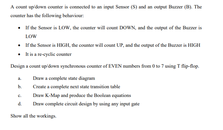
A count up/down counter is connected to an input Sensor (S) and an output Buzzer (B). The counter has the following behaviour: If the Sensor is LOW, the counter will count DOWN, and the output of the Buzzer is LOW If the Sensor is HIGH, the counter will count UP, and the output of the Buzzer is HIGH It is a re-cyclic counter Design a count up/down synchronous counter of EVEN numbers from 0 to 7 using T flip-flop. a. b. Draw a complete state diagram Create a complete next state transition table Draw K-Map and produce the Boolean equations Draw complete circuit design by using any input gate c. d. Show all the workings
Step by Step Solution
There are 3 Steps involved in it
1 Expert Approved Answer
Step: 1 Unlock

Question Has Been Solved by an Expert!
Get step-by-step solutions from verified subject matter experts
Step: 2 Unlock
Step: 3 Unlock