

Question: a. Derive the transfer function for the Spring-Mass-Damper system shown in figure 1 mathematically. b- Draw the block diagram for the system. C- Enter the
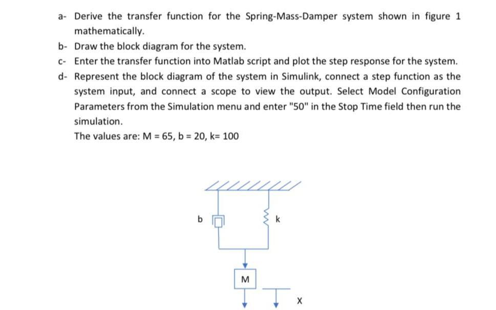
a. Derive the transfer function for the Spring-Mass-Damper system shown in figure 1 mathematically. b- Draw the block diagram for the system. C- Enter the transfer function into Matlab script and plot the step response for the system. d- Represent the block diagram of the system in Simulink, connect a step function as the system input, and connect a scope to view the output. Select Model Configuration Parameters from the Simulation menu and enter "50" in the Stop Time field then run the simulation. The values are: M = 65, b = 20, k= 100 44 b k M
Step by Step Solution
There are 3 Steps involved in it
1 Expert Approved Answer
Step: 1 Unlock

Question Has Been Solved by an Expert!
Get step-by-step solutions from verified subject matter experts
Step: 2 Unlock
Step: 3 Unlock