

Question: a. Design a 1-to-2 decoder using structure model as the following circuit: Figure 1: 1-to-2 decoder a. Write a test bench for the 2-to-1 Multiplexer
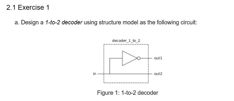
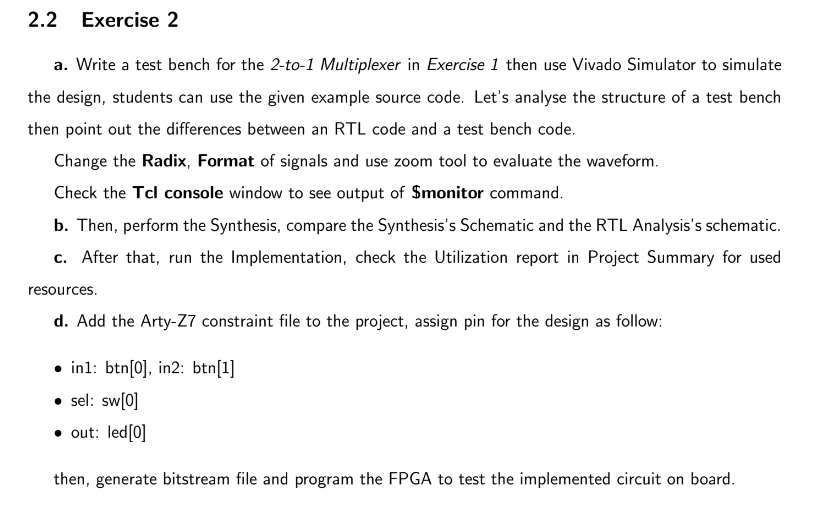
a. Design a 1-to-2 decoder using structure model as the following circuit: Figure 1: 1-to-2 decoder a. Write a test bench for the 2-to-1 Multiplexer in Exercise 1 then use Vivado Simulator to simulate the design, students can use the given example source code. Let's analyse the structure of a test bench then point out the differences between an RTL code and a test bench code. Change the Radix, Format of signals and use zoom tool to evaluate the waveform. Check the Tcl console window to see output of \$monitor command. b. Then, perform the Synthesis, compare the Synthesis's Schematic and the RTL Analysis's schematic. c. After that, run the Implementation, check the Utilization report in Project Summary for used resources. d. Add the Arty-Z7 constraint file to the project, assign pin for the design as follow: - in1: btn[0], in2: btn[1] - sel: sw[0] - out: led[0] then, generate bitstream file and program the FPGA to test the implemented circuit on board
Step by Step Solution
There are 3 Steps involved in it

Get step-by-step solutions from verified subject matter experts