

Question: A digital system is modelled by the RTL code in Listing Q1. Assume that a, b and c are external inputs, and the registers
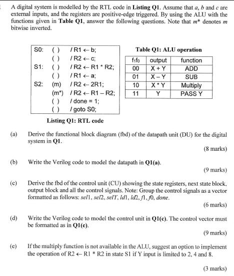
A digital system is modelled by the RTL code in Listing Q1. Assume that a, b and c are external inputs, and the registers are positive-edge triggered. By using the ALU with the functions given in Table Q1, answer the following questions. Note that m* denotes m bitwise inverted. SO: () /R1 b; Table Q1: ALU operation (a) ( ) /R2 C fifo output function S1: ( ) /R2 R1 R2; 00 X+Y ADD ( ) /R1a; 01 X-Y SUB S2: (m) /R2
Step by Step Solution
There are 3 Steps involved in it
1 Expert Approved Answer
Step: 1 Unlock

Question Has Been Solved by an Expert!
Get step-by-step solutions from verified subject matter experts
Step: 2 Unlock
Step: 3 Unlock