

Question: a) Draw the Flash dan Data Memory map of the AVR processor showing the General-Purpose Registers, I/O Registers, General-Purpose Data, Stack, Interrupt Vector Table, Boot
a) Draw the Flash dan Data Memory map of the AVR processor showing the General-Purpose Registers, I/O Registers, General-Purpose Data, Stack, Interrupt Vector Table, Boot Section, and Program Section. Explain the purpose of each memory space.
(b) Write directives to: i. Reserve 10 bytes with a label myTab in the RAM location 0x100. ii. Initialize a value of 0x1A with a label myConst in the EEPROM location 0x10. iii. Initialize a value of 0xABCD with a label myWord in the Flash Memory location 0x80.
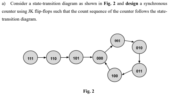
a) Consider a state-transition diagram as shown in Fig. 2 and design a synchronous counter using JK flip-flops such that the count sequence of the counter follows the state- transition diagram. 001 010 111 110 101 000 011 100 Fig. 2
Step by Step Solution
There are 3 Steps involved in it

Get step-by-step solutions from verified subject matter experts