

Question: a) Figure 1 shows a logic circuit having two inputs (A, and B) and 3 outputs (X1, X2 and X3). Use MMLogic to build the
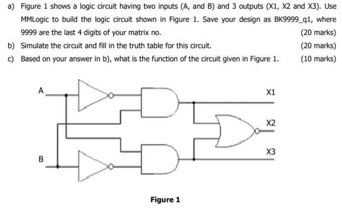
a) Figure 1 shows a logic circuit having two inputs (A, and B) and 3 outputs (X1, X2 and X3). Use MMLogic to build the logic circuit shown in Figure 1. Save your design as BK9999_q1, where 9999 are the last 4 digits of your matrix no. (20 marks) b) Simulate the circuit and fill in the truth table for this circuit. (20 marks) c) Based on your answer in b), what is the function of the circuit given in Figure 1. (10 marks) Figure 1
Step by Step Solution
There are 3 Steps involved in it
1 Expert Approved Answer
Step: 1 Unlock

Question Has Been Solved by an Expert!
Get step-by-step solutions from verified subject matter experts
Step: 2 Unlock
Step: 3 Unlock