

Question: A gear reduction unit uses the countershaft shown in Fig. 1. Gear A receives power from another gear with the transmitted force FA =
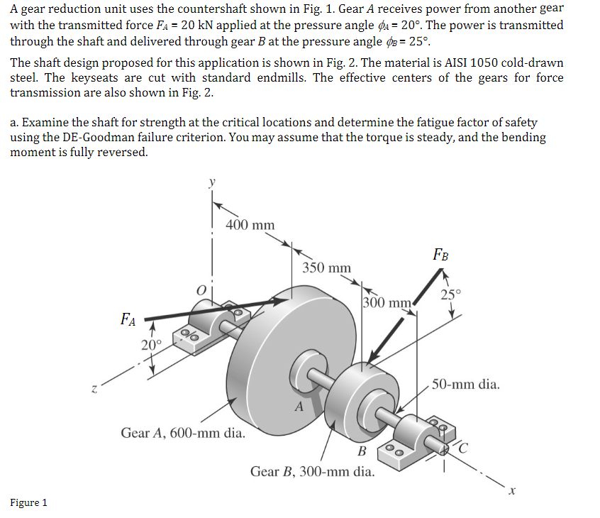
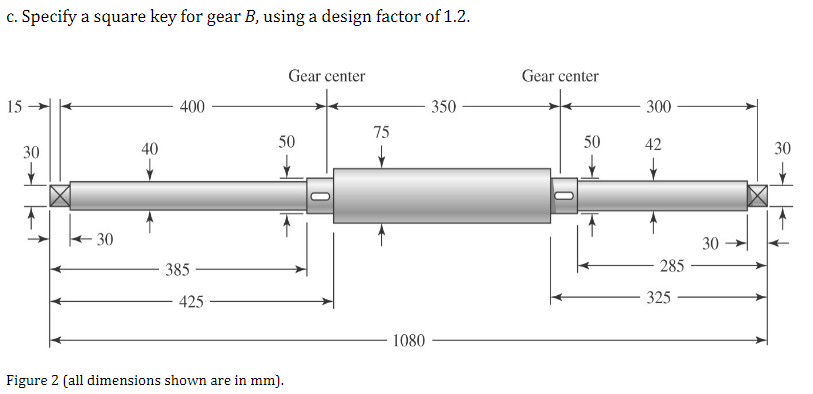
A gear reduction unit uses the countershaft shown in Fig. 1. Gear A receives power from another gear with the transmitted force FA = 20 kN applied at the pressure angle = 20. The power is transmitted through the shaft and delivered through gear B at the pressure angle = 25. The shaft design proposed for this application is shown in Fig. 2. The material is AISI 1050 cold-drawn steel. The keyseats are cut with standard endmills. The effective centers of the gears for force transmission are also shown in Fig. 2. a. Examine the shaft for strength at the critical locations and determine the fatigue factor of safety using the DE-Goodman failure criterion. You may assume that the torque is steady, and the bending moment is fully reversed. Figure 1 FA 20 y 400 mm FB 350 mm 25 300 mm A Gear A, 600-mm dia. B Gear B, 300-mm dia. 50-mm dia. /C c. Specify a square key for gear B, using a design factor of 1.2. 15 40 30 400 Gear center Gear center 350 300 75 50 50 42 30 30 385 425 Figure 2 (all dimensions shown are in mm). 0 1080 30 285 325
Step by Step Solution
There are 3 Steps involved in it

Get step-by-step solutions from verified subject matter experts