

Question: (a) Given the Howe Truss with loads as shown, determine the external reaction forces at the restraints A & G. (Be sure to show
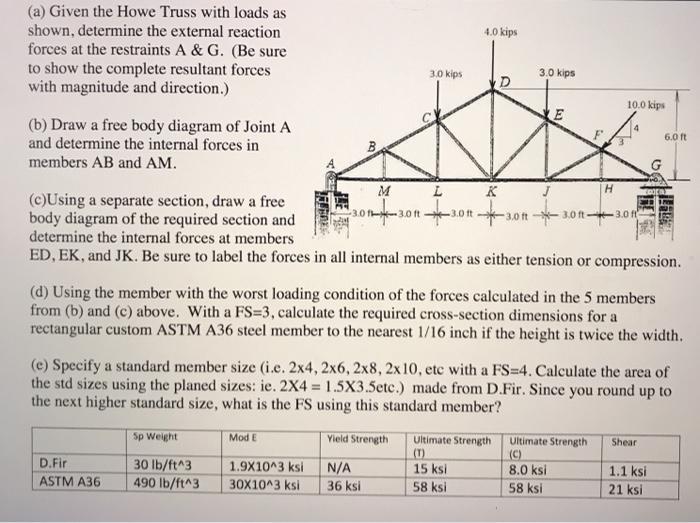
(a) Given the Howe Truss with loads as shown, determine the external reaction forces at the restraints A & G. (Be sure to show the complete resultant forces with magnitude and direction.) 4.0 kips 3.0 kips 3.0 kips D 10.0 kips (b) Draw a free body diagram of Joint A and determine the internal forces in members AB and AM. 6.0 ft M K H (c)Using a separate section, draw a free body diagram of the required section and determine the internal forces at members ED, EK, and JK. Be sure to label the forces in all internal members as either tension or compression. 10 f--3.0 ft -3.0 ft 3.0 ft 3.0 ft -3.0 f (d) Using the member with the worst loading condition of the forces calculated in the 5 members from (b) and (c) above. With a FS=3, calculate the required cross-section dimensions for a rectangular custom ASTM A36 steel member to the nearest 1/16 inch if the height is twice the width. (e) Specify a standard member size (i.e. 2x4, 2x6, 2x8, 2x 10, etc with a FS=4. Calculate the area of the std sizes using the planed sizes: ie. 2X4 1.5X3.5ete.) made from D.Fir. Since you round up to the next higher standard size, what is the FS using this standard member? Sp Weight Mod E Yield Strength Ultimate Strength (T) 15 ksi Ultimate Strength (C) 8.0 ksi Shear D.Fir 30 lb/ft^3 490 lb/ft^3 1.9X10^3 ksi N/A 1.1 ksi ASTM A36 30X10^3 ksi 36 ksi 58 ksi 58 ksi 21 ksi
Step by Step Solution
3.53 Rating (170 Votes )
There are 3 Steps involved in it

Get step-by-step solutions from verified subject matter experts