

Question: A group of EBE students are designing a double - reduction spur gear train set as shown in Figure 2 . The shaft a is
A group of EBE students are designing a doublereduction spur gear train set as shown in Figure The shaft is driven by a motor attached by a flexible coupling attached to the overhang. The gears have pressure angles, with the numbers of teeth as The module for all gears is mm
The motor rotates at a speed of rpm and provides a torque with its value assigned by using the last digits of your sID divided by taking a unit of Nm see an example below Assuming a efficiency for the power transmission.
Torque parameter determination example: Suppose your sID is S then the torque parameter for you is:
The input shaft is to be machined using an AISI colddrawn steel. A general shaft layout is shown in Figure b A design factor of is required.
a
b
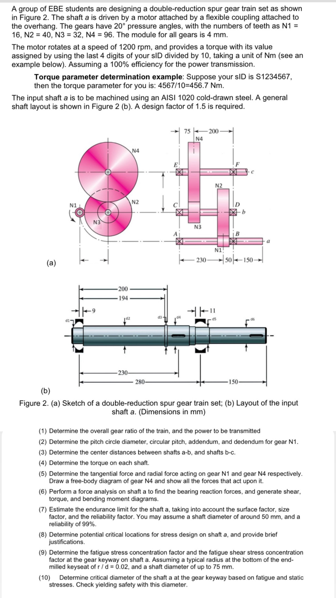
Figure a Sketch of a doublereduction spur gear train set; b Layout of the input shaft aDimensions in mm
Determine the overall gear ratio of the train, and the power to be transmitted
Determine the pitch circle diameter, circular pitch, addendum, and dedendum for gear N
Determine the center distances between shafts ab and shafts bc
Determine the torque on each shaft.
Determine the tangential force and radial force acting on gear N and gear N respectively. Draw a freebody diagram of gear N and show all the forces that act upon it
Perform a force analysis on shaft a to find the bearing reaction forces, and generate shear, torque, and bending moment diagrams.
Estimate the endurance limit for the shaft a taking into account the surface factor, size factor, and the reliability factor. You may assume a shaft diameter of around mm and a reliability of
Determine potential critical locations for stress design on shaft and provide brief justifications.
Determine the fatigue stress concentration factor and the fatigue shear stress concentration factor at the gear keyway on shaft a Assuming a typical radius at the bottom of the endmilled keyseat of and a shaft diameter of up to mm
Determine critical diameter of the shaft a at the gear keyway based on fatigue and static stresses. Check yielding safety with this diameter.
Step by Step Solution
There are 3 Steps involved in it
1 Expert Approved Answer
Step: 1 Unlock

Question Has Been Solved by an Expert!
Get step-by-step solutions from verified subject matter experts
Step: 2 Unlock
Step: 3 Unlock