

Question: A hypothetical logic circuit sometimes known as a half - subtractor can be created by combining exactly three logic gates. Similar to the need for
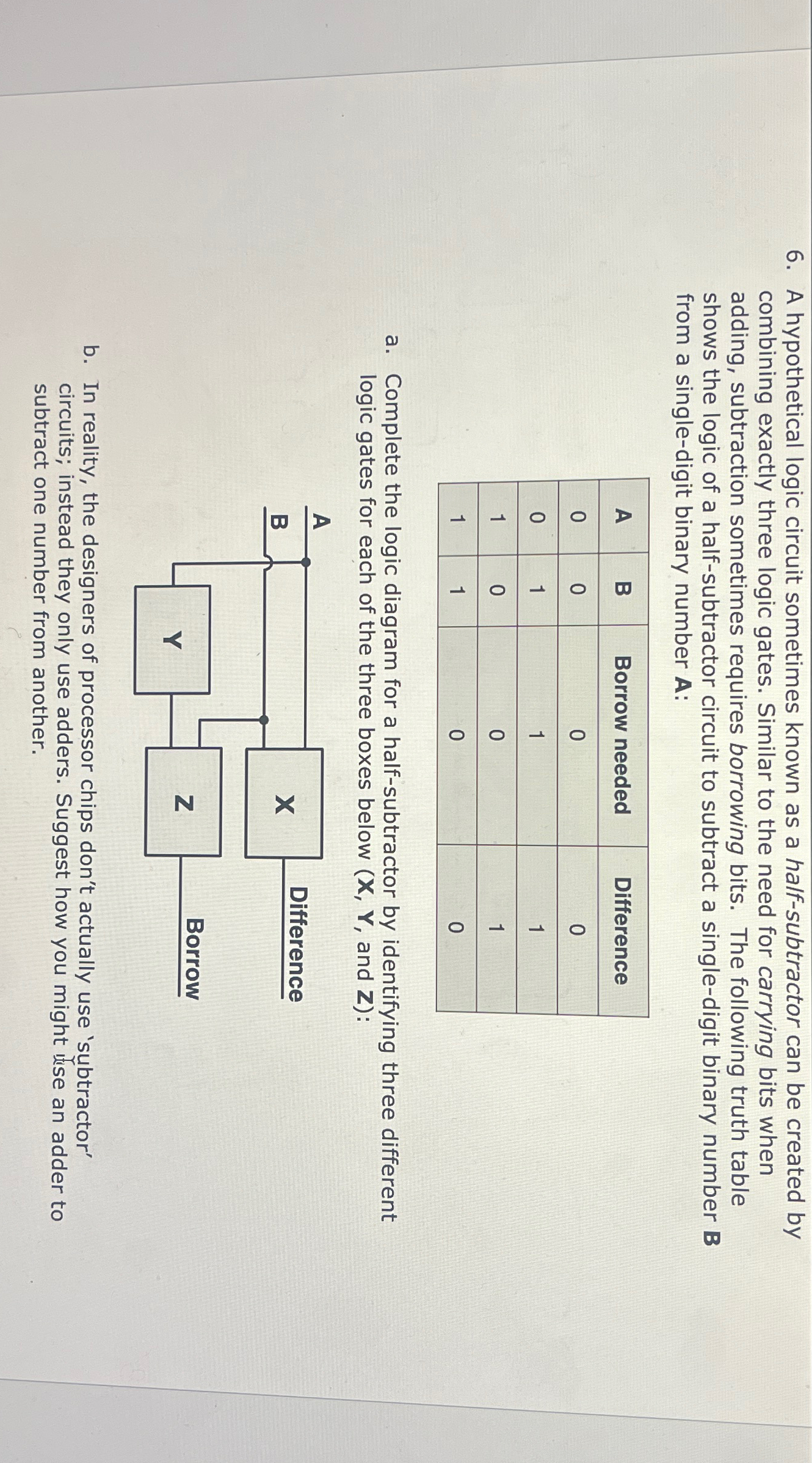
A hypothetical logic circuit sometimes known as a halfsubtractor can be created by combining exactly three logic gates. Similar to the need for carrying bits when adding, subtraction sometimes requires borrowing bits. The following truth table shows the logic of a halfsubtractor circuit to subtract a singledigit binary number from a singledigit binary number :
tableABBorrow needed,Difference
a Complete the logic diagram for a halfsubtractor by identifying three different logic gates for each of the three boxes below and :
b In reality, the designers of processor chips don't actually use 'subtractor' circuits; instead they only use adders. Suggest how you might ise an adder to subtract one number from another.
Step by Step Solution
There are 3 Steps involved in it
1 Expert Approved Answer
Step: 1 Unlock

Question Has Been Solved by an Expert!
Get step-by-step solutions from verified subject matter experts
Step: 2 Unlock
Step: 3 Unlock