

Question: ( a ) Overvie ( b ) Zoom - it at the botti the shaft ( c ) Zoom - in top view of the
a Overvie
b Zoomit
at the botti
the shaft
c Zoomin "top" view of the solid
Particle at the bottom of the
middle of the shaft
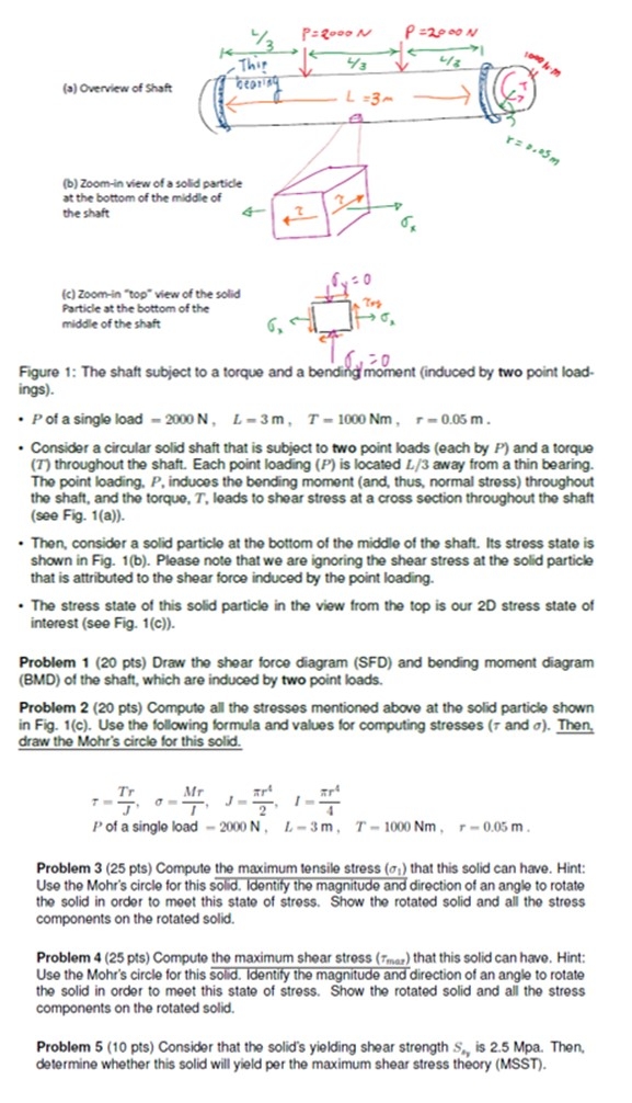
Figure : The shaft subject to a torque and a venaing moment induced by two point loadings
of a single load
Consider a circular solid shaft that is subject to two point loads each by and a torque throughout the shaft. Each point loading is located away from a thin bearing. The point loading, induces the bending moment and thus, normal stress throughout the shaft, and the torque, leads to shear stress at a cross section throughout the shaft see Fig. a
Then, consider a solid particle at the bottom of the middle of the shaft. Its stress state is shown in Fig. b Please note that we are ignoring the shear stress at the solid particle that is attributed to the shear force induced by the point loading.
The stress state of this solid particle in the view from the top is our D stress state of interest see Fig. c
Problem pts Draw the shear force diagram SFD and bending moment diagram BMD of the shaft, which are induced by two point loads.
Problem pts Compute all the stresses mentioned above at the solid particle shown in Fig. c Use the following formula and values for computing stresses and Then, draw the Mohr's circle for this solid.
a single load
Problem pts Compute the maximum tensile stress :
Step by Step Solution
There are 3 Steps involved in it
1 Expert Approved Answer
Step: 1 Unlock

Question Has Been Solved by an Expert!
Get step-by-step solutions from verified subject matter experts
Step: 2 Unlock
Step: 3 Unlock