

Question: A pipe-rod system with flanges at ends A and C was supposed to fit exactly between two rigid walls. Element 1 is a steel
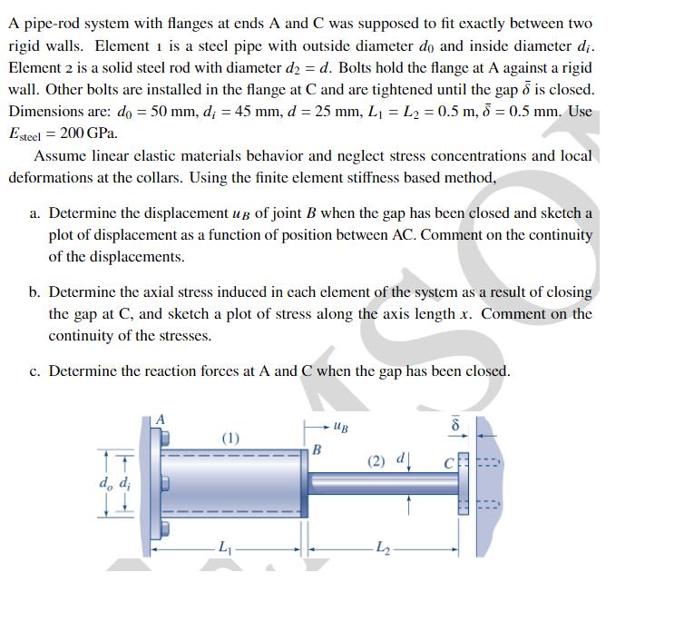
A pipe-rod system with flanges at ends A and C was supposed to fit exactly between two rigid walls. Element 1 is a steel pipe with outside diameter do and inside diameter di. Element 2 is a solid steel rod with diameter d2 = d. Bolts hold the flange at A against a rigid wall. Other bolts are installed in the flange at C and are tightened until the gap 8 is closed. Dimensions are: do = 50 mm, d; = 45 mm, d = 25 mm, L= L = 0.5 m, 6 = 0.5 mm. Use Esteel = 200 GPa. Assume linear elastic materials behavior and neglect stress concentrations and local deformations at the collars. Using the finite element stiffness based method, a. Determine the displacement ug of joint B when the gap has been closed and sketch a plot of displacement as a function of position between AC. Comment on the continuity of the displacements. b. Determine the axial stress induced in each element of the system as a result of closing the gap at C, and sketch a plot of stress along the axis length x. Comment on the continuity of the stresses. c. Determine the reaction forces at A and C when the gap has been closed. IT do di A (1) L B UB (2) d 42. C B L
Step by Step Solution
3.41 Rating (167 Votes )
There are 3 Steps involved in it

Get step-by-step solutions from verified subject matter experts