

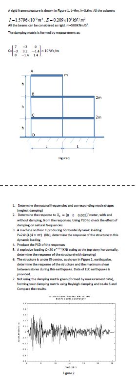
Question: A rigid frame structure bs shown in Figure 1 . 1 - 6 m , I - 3 . 6 m . All the columes
A rigid frame structure bs shown in Figure m Im All the columes
All the bearms can be considered as rigid.
The damping matrix is formed by meruurement inc:
Detarmine the natural frequencies and correpponding mode shapes
neylect damping
Determine the response to meter, with and
without damping, from the respontes, Using PSD to check the effect of
damping os nataral frequencies.
A machine on floor C producing horlestal dynamic loading
KNQ determine the response of the structure to this
dynamic loading
Produce the PSD of the telyonses
A erplosive loading acting at the top story horitoetally,
determine the recponse of the structurediwith damping
The structure is under Elcentro, an showe in Figure earthquake,
determise the response of the stactore and the maximum shear
between sheres during this earthquake. Data of ELC earthquake is
pervided.
Not using the damping mavie given formed by measarement data
forming your damping matrix using Rayleigh damping and redo and
Compare the results.
Step by Step Solution
There are 3 Steps involved in it
1 Expert Approved Answer
Step: 1 Unlock

Question Has Been Solved by an Expert!
Get step-by-step solutions from verified subject matter experts
Step: 2 Unlock
Step: 3 Unlock