

Question: A rotating machine is mounted on two shock mounts as shown in Figure A1-1 (it rotates about the axis coming out of the paper,
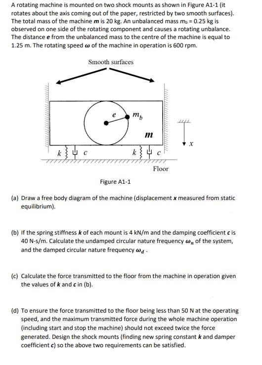
A rotating machine is mounted on two shock mounts as shown in Figure A1-1 (it rotates about the axis coming out of the paper, restricted by two smooth surfaces). The total mass of the machine m is 20 kg. An unbalanced mass mb = 0.25 kg is observed on one side of the rotating component and causes a rotating unbalance. The distance e from the unbalanced mass to the centre of the machine is equal to 1.25 m. The rotating speed of the machine in operation is 600 rpm. Smooth surfaces m . x Floor Figure A1-1 (a) Draw a free body diagram of the machine (displacement x measured from static equilibrium). (b) If the spring stiffness k of each mount is 4 kN/m and the damping coefficient c is 40 N-s/m. Calculate the undamped circular nature frequency w of the system, and the damped circular nature frequency wa (c) Calculate the force transmitted to the floor from the machine in operation given the values of k and c in (b). (d) To ensure the force transmitted to the floor being less than 50 N at the operating speed, and the maximum transmitted force during the whole machine operation (including start and stop the machine) should not exceed twice the force generated. Design the shock mounts (finding new spring constant k and damper coefficient c) so the above two requirements can be satisfied.
Step by Step Solution
There are 3 Steps involved in it

Get step-by-step solutions from verified subject matter experts