

Question: 4. A simple closed-loop system with a proportional controller is shown in Fig. 3 and its root locus is shown in Fig. 4. Reference
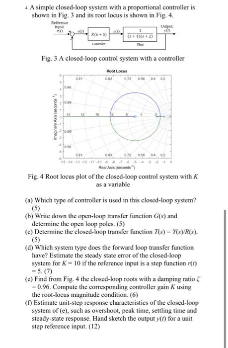
4. A simple closed-loop system with a proportional controller is shown in Fig. 3 and its root locus is shown in Fig. 4. Reference input Output, K(s + 5) (s+ 1)(s+ 2) Controler Fig. 3 A closed-loop control system with a controller Root Locus 083 072 ase 04 02 20.99 14 12 0.72 056 04 02 s -14 -13 -12 -11 -10 Real Axis (seconds") Fig. 4 Root locus plot of the closed-loop control system with K as a variable (a) Which type of controller is used in this closed-loop system? (5) (b) Write down the open-loop transfer function G(s) and determine the open loop poles. (5) (c) Determine the closed-loop transfer function T(s) = Y(s)/R(s). (5) (d) Which system type does the forward loop transfer function have? Estimate the steady state error of the closed-loop system for K = 10 if the reference input is a step function r(1) = 5. (7) (e) Find from Fig. 4 the closed-loop roots with a damping ratio5 = 0.96. Compute the corresponding controller gain K using the root-locus magnitude condition. (6) () Estimate unit-step response characteristics of the closed-loop system of (e), such as overshoot, peak time, settling time and steady-state response. Hand sketch the output y(1) for a unit step reference input. (12) Imaginary Axis (seconds")
Step by Step Solution
3.33 Rating (150 Votes )
There are 3 Steps involved in it

Get step-by-step solutions from verified subject matter experts