

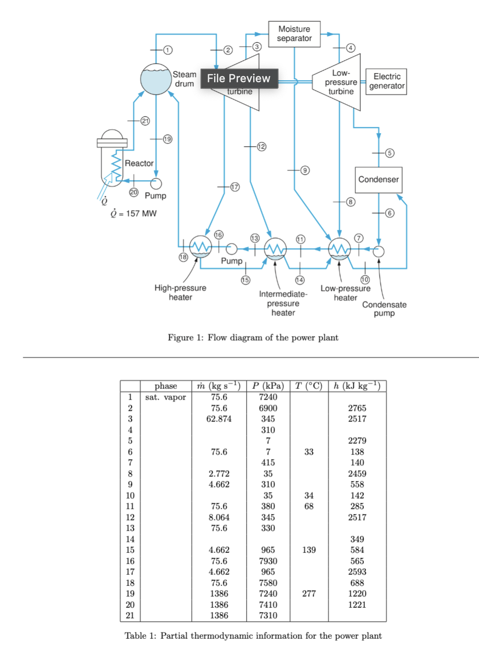
Question: A simplified flow diagram for a ( relatively low power ) pressurized water reactor ( PWR ) nuclear power plant is given in Fig. 1
A simplified flow diagram for a relatively low power pressurized water reactor PWR nuclear power plant is given
in Fig. Partial information on the various states in the cycle is shown in Table
In contrast to a boiling water reactor BWR the water in the reactor of a PWR is pressurized to suppress boiling
as much as possible. The pressurized water is heated in the reactor, which supplies MW of heat, and is then
transferred from the reactor to a steam drum to produce the steam that drives the turbines. Saturated vapor leaves
the steam drum to power the turbines while liquid water is pumped from the steam drum back to the reactor
The cycle implements regenerative feed heating where small amounts of steam are bled off from the highpressure
and lowpressure turbines to feedwater heaters Waste heat primarily leaves the cycle in the condenser.
For your analysis, you may assume that any individual component of the system ie any pump, turbine, condenser,
etc. is a reversible process.
For your analysis, you may assume that any individual component of the system other than the reactor and the
condenser ie any pump, turbine, regenerative heat exchanger is approximately adiabatic from an energetic
perspective ieQ mh so Q in a firstlaw analysis You may also assume that the pumps and turbines are
approximately reversible from an energetic perspective, in the sense that you do not have to consider any lost work
in the turbines or pumps. However, the system may not be taken as approximately isentropic in the sense that we
cannot say that QT Sgen is negligible in an entropy analysis of the components.
For the power plant, complete the following:
a Find values for all missing entries for phase, m P T and h in Table you may skip P and T for state
b Find the quality at assuming the moisture separator is adiabatic
c Find the power output of the highpressure turbine
d Find the power output of the lowpressure turbine
e Find the thermal efficiency of the power plant
f Find the quality of the steam leaving the reactor at
g Find the power that the pump that feeds water to the reactor transfers to the water
h Find the power that the pump that feeds water to the highpressure heater transfers to the water
i Find the power that the pump that feeds water to the lowpressure heater transfers to the water
e Find the thermal efficiency of the power plant
j Find an upper limit to the temperature of the heat sink used by the condenser for the same net power output of
the plant if the temperature of the heat source is assumed to be equal to the temperature of the water leaving
the reactor
k Find the amount of leaked waste heat over the cycle ie heat lost in parts of the cycle other than the condenser
Figure : Flow diagram of the power plant
Table : Partial thermodynamic information for the power plant
Step by Step Solution
There are 3 Steps involved in it
1 Expert Approved Answer
Step: 1 Unlock

Question Has Been Solved by an Expert!
Get step-by-step solutions from verified subject matter experts
Step: 2 Unlock
Step: 3 Unlock