

Question: A simply supported beam with 1 4 - feet span has a rectangular section having ( b = 1 4 mathrm { in
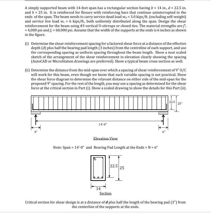
A simply supported beam with feet span has a rectangular section having bmathrmin dmathrmin and hmathrmin It is reinforced for flexure with reinforcing bars that continue uninterrupted to the ends of the span. The beam needs to carry service dead load mathrmwDmathrmkipsmathrmftexcluding selfweight and service live load mathrmwLmathrmkipsmathrmft both uniformly distributed along the span. Design the shear reinforcement for the beam using # vertical U stirrups or closed ties. The material strengths are fcprimemathrmpsi and fymathrmpsi Assume that the width of the supports at the ends is inches as shown in the figure.
i Determine the shear reinforcement spacing for a factored shear force at a distance of the effective depth d plus half the bearing pad length inches from the centreline of each support, and use the corresponding spacing as uniform spacing throughout the beam length. Show a neat scaled sketch of the arrangement of the shear reinforcement in elevation clearly showing the spacing AutoCAD or MicroStation drawings are preferred Show a typical beam crosssection as well.
ii Determine the distance from the midspan over which a spacing of shear reinforcement of prime primemathrmOmathrmC will work for this beam, even though we know that such variable spacing is not practical. Show the shear force diagram to determine the relavant distance on either side of the midspan for the proposed spacing. For the rest of the length, you may use a spacing as determined for the shear force at the critical section in Part i Show a scaled drawing to show the details for this Part ii
Elevation View
Note: Span primeprime prime and Bearing Pad Length at the Ends mathrmNprime prime
Critical section for shear design is at a distance of boldsymbold plus half the length of the bearing pad prime prime from the centerline of the supports at the ends.
Step by Step Solution
There are 3 Steps involved in it
1 Expert Approved Answer
Step: 1 Unlock

Question Has Been Solved by an Expert!
Get step-by-step solutions from verified subject matter experts
Step: 2 Unlock
Step: 3 Unlock