

Question: A single - phase transformer circuit is to be designed. The transformer parameters ( turns ratio, the primary voltage ( V 1 ) , the
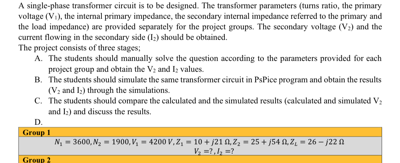
A singlephase transformer circuit is to be designed. The transformer parameters turns ratio, the primary voltage the internal primary impedance, the secondary internal impedance referred to the primary and the load impedance are provided separately for the project groups. The secondary voltage and the current flowing in the secondary side should be obtained.
The project consists of three stages;
A The students should manually solve the question according to the parameters provided for each project group and obtain the and values.
B The students should simulate the same transformer circuit in PsPice program and obtain the results and through the simulations.
C The students should compare the calculated and the simulated results calculated and simulated and and discuss the results.
D
Group
Step by Step Solution
There are 3 Steps involved in it
1 Expert Approved Answer
Step: 1 Unlock

Question Has Been Solved by an Expert!
Get step-by-step solutions from verified subject matter experts
Step: 2 Unlock
Step: 3 Unlock