

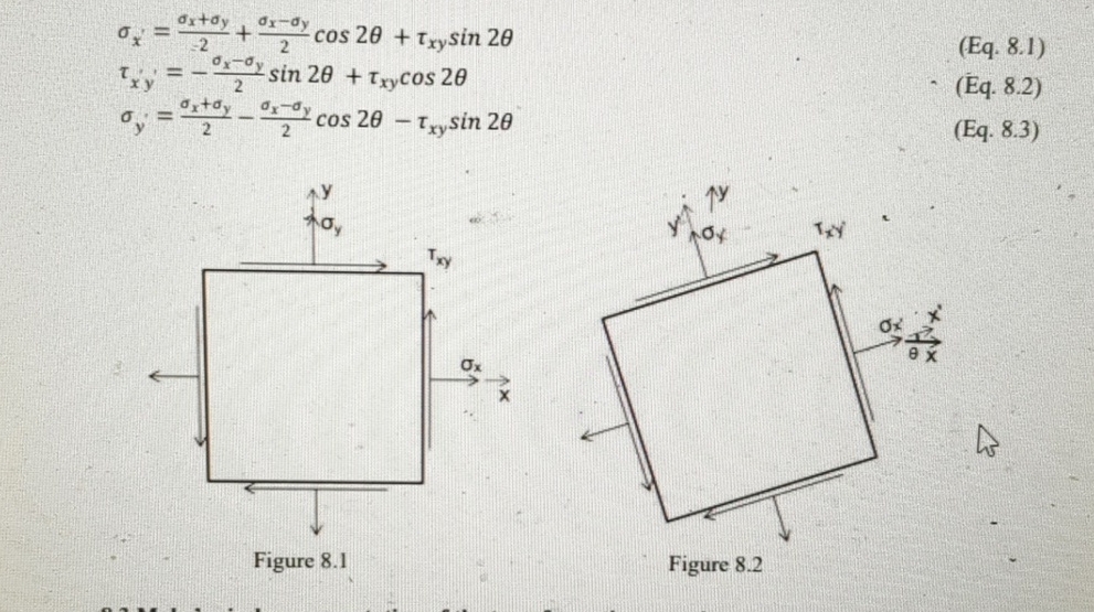
Question: ( a ) Sketch the element for which the normal and shearing stresses are known or have been calculated ( Figure 8 . 4 )
a Sketch the element for which the normal and shearing stresses are known or have been calculated Figure Show the actual directions of the stresses.
Laboratory Civ E
b Establish a set of rectangular coordinate axes for plotting the Mohr's circle Figure The horizontal axis is used to plot normal stresses and the vertical axis is used to plot shear stresses Label the axes and show the sign conventions.
c Locate the center of the Mohr's circle on the horizontal axis, as the point with abscissa
d Plot the point on the circle corresponding to the stress conditions on the face perpendicular to the x axis ie and The normal stress value is plotted as positive or negative depending on whether the stress is tensile or compressive. However, a special rule that is specific to the plotting of the Mohr's circle must be used to distinguish between shear stresses that tend to rotate the element clockwise versus those tending to rotate it counterclockwise. On any element there will always be two of each. If the shear stress is clockwise, the point is plotted above the axis and if it is counterclockwise, the point is plotted below the axis. Thus, in the present example, the point X on the Mohr's circle in Figure is the point associated with the plane perpendicular to the x axis,
e Following the same general procedure outlined in d plot the point on the Mohr's circle associated with the plane perpendicular to the axis. This gives point in Figure Note that it and point are at the opposite ends of a diameter.
f Having established both the center and a diameter of the circle, the complete circle can now be drawn.
g With the geometry of the circle established, the values of the stresses acting on any element can be calculated. For example, consider the rotated element in Figure The face perpendicular to the axis is oriented at an angle counterclockwise from the face perpendicular to the axis. The corresponding point on the circle is obtained by starting at and rotating through an angle Note that the direction of rotation on the circle is the same as the direction of rotation between the planes. The point at the other end of the diameter from is associated with the plane perpendicular to the axis. The coordinates of points and can be determined from the geometry of the circle using trigonometry. To determine the direction of the normal and shear stresses on these planes, the rules used in step d must be followed.
h The values the maximum shear stress and the principal stresses can be determined by considering the vertical and horizontal diameters respectively. The orientation of the corresponding planes can also be determined.
Eq
Eq
Eq
Figure
Step by Step Solution
There are 3 Steps involved in it
1 Expert Approved Answer
Step: 1 Unlock

Question Has Been Solved by an Expert!
Get step-by-step solutions from verified subject matter experts
Step: 2 Unlock
Step: 3 Unlock