

A stiffened web beam is shown in the following sketch. The loads shown are 'ultimate design loads'
No answer yet for this question.
Ask a Tutor
Question:
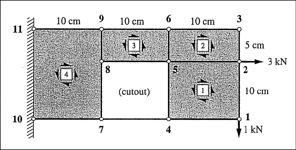
A stiffened web beam is shown in the following sketch. The loads shown are 'ultimate design loads' that are greater than the loads actually intended to be placed on the structure by an appropriate factor of safety, hence no further factors of safety will need to be used in this problem. Assume that all parts of the structure are made of aluminum alloy with E = 70GPa and =0.33. On wall 10-11 the shear web supports the full shear resultant while there are horizontal reaction forces at 10 and 11 only.
- Determine the shear flows in each of the webs, q1, q2, q3, and q4assuming the webs do not buckle. Use the sign conventions in the sketch.
- Sketch the axial load as a function of x (where x is a horizontal axis) for the horizontally oriented stiffener 1-4-7-10. Indicate numerical values of the load at each joint. Use + for tension and - for compression.
- Assuming that the thickness of the web 2 is controlled by shear buckling determine the minimum acceptable thickness of web 2 (only). Assume simply supported boundary conditions on the edges of the panel.
- (Consider the longitudinal stiffener loaded in tension, 9-11. If the normal stress in this stiffener is to be limited to a maximum of 275MPa, determine the minimum acceptable cross-section area for the stiffener. The cross-section is uniform along the stiffener.
Expert Answer:

Related Book For 
Posted Date:
