

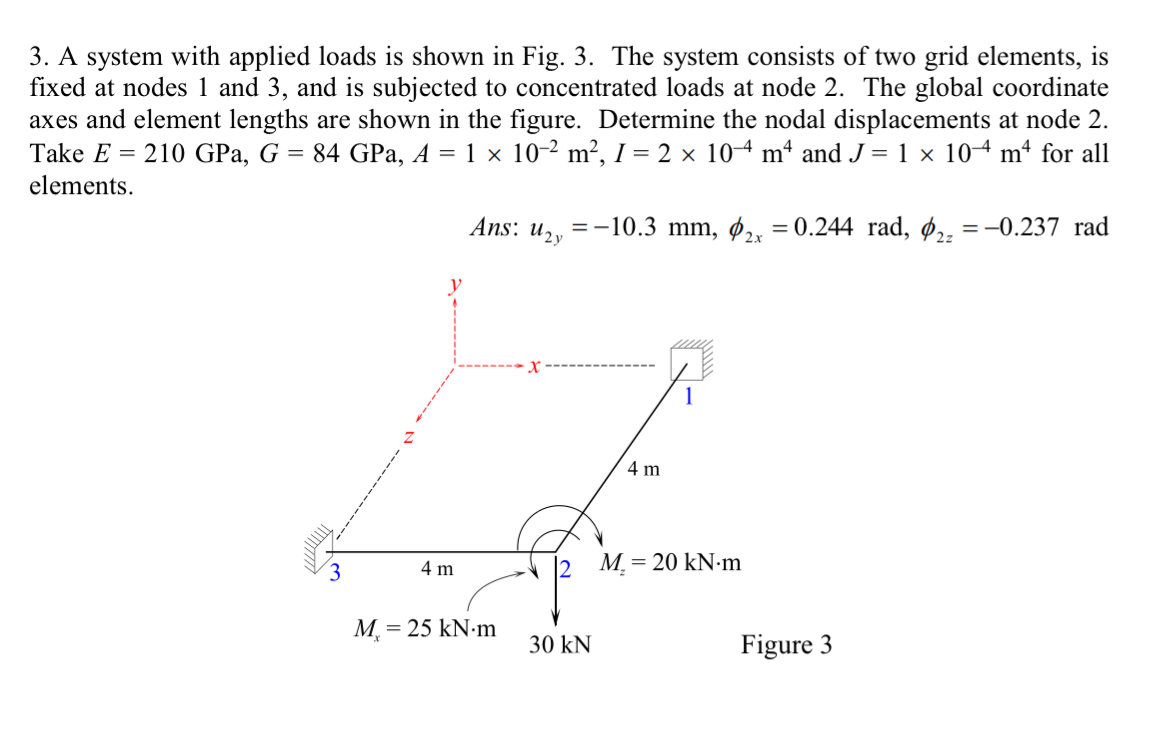
Question: A system with applied loads is shown in Fig. 3 . The system consists of two grid elements, is fixed at nodes 1 and 3
A system with applied loads is shown in Fig. The system consists of two grid elements, is
fixed at nodes and and is subjected to concentrated loads at node The global coordinate
axes and element lengths are shown in the figure. Determine the nodal displacements at node
Take GPa,GPa, and for all
elements.
Ans: rad,rad
Step by Step Solution
There are 3 Steps involved in it
1 Expert Approved Answer
Step: 1 Unlock

Question Has Been Solved by an Expert!
Get step-by-step solutions from verified subject matter experts
Step: 2 Unlock
Step: 3 Unlock