

Question: a) The first part of the design involves converting the BCD into its equivalent binary magnitude (Eg: -34 and 34 in BCD are both converted
-
a) The first part of the design involves converting the BCD into its equivalent binary magnitude (Eg: -34 and 34 in BCD are both converted to 00100010 in binary magnitude). In this design, you can use n-b it adders and multipliers with 2 4-bit inputs and one 8-bit output.
-
b) Now, we will convert the binary representation of A and B, into their equivalent 2s complement notation. At this step, we will take into account whether we are adding or subtracting A and B, using gate MG. What is the truth table for MG?
-
c) We wish to create an overflow detector, which can detect the nature of the overflow. The output O from the adder is set to 1 if an overflow is detected. If there is no overflow, we set E1 =0 and E2 =0. If an overflow is detected, and the final sum 127, then we set E1 =1 and E2 =1, . Identify the truth table for E1 and E2 in terms of As ign, Bs ign and O, and implement it using only NAND and NOT gates.
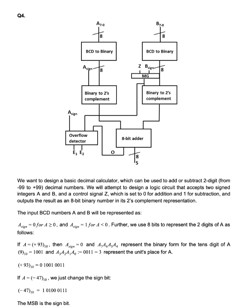
Q4. A7-0 B7-0 8 BCD to Binary BCD to Binary Asign z Bsigo 18 18 MG Binary to 2's complement Binary to 2's complement Asien Overflow detector 8-bit adder E1 E2 0 8 We want to design a basic decimal calculator, which can be used to add or subtract 2-digit (from -99 to +99) decimal numbers. We will attempt to design a logic circuit that accepts two signed integers A and B, and a control signal Z, which is set to 0 for addition and 1 for subtraction, and outputs the result as an 8-bit binary number in its 2's complement representation. The input BCD numbers A and B will be represented as: Asign = 0 for A 20, and Asign = 1 for A
Step by Step Solution
There are 3 Steps involved in it

Get step-by-step solutions from verified subject matter experts