

Question: The figure shows the physical part of a load-positioning system without the sensors and the controller electronics that control the voltage source. You are
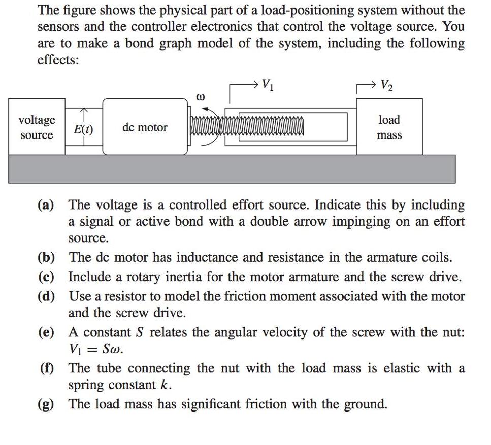
The figure shows the physical part of a load-positioning system without the sensors and the controller electronics that control the voltage source. You are to make a bond graph model of the system, including the following effects: V1 V2 voltage load dc motor E(t) source mass (a) The voltage is a controlled effort source. Indicate this by including a signal or active bond with a double arrow impinging on an effort source. (b) The dc motor has inductance and resistance in the armature coils. (c) Include a rotary inertia for the motor armature and the screw drive. (d) Use a resistor to model the friction moment associated with the motor and the screw drive. A constant S relates the angular velocity of the screw with the nut: Vi = So. (f) The tube connecting the nut with the load mass is elastic with a spring constant k. (g) (e) The load mass has significant friction with the ground.
Step by Step Solution
3.37 Rating (150 Votes )
There are 3 Steps involved in it

Get step-by-step solutions from verified subject matter experts
Document Format (2 attachments)
635e1f828cfc6_181650.pdf
180 KBs PDF File
635e1f828cfc6_181650.docx
120 KBs Word File