

Question: A vibrating sieve will be made for use in a sieving process. A general schematic representation of this sieve design is given in Figure 1
A vibrating sieve will be made for use in a sieving process. A general schematic representation of this sieve design is given in Figure 1 as a top view. It is desirable to design and analyze the system by taking into account the constraints given in the numbered questions below. The sieve mass is M=4 kg.
1) design an experimental device to determine the natural frequency of the system and explain it by drawing the devices you will use. (method and formulas to be used should be explained)
2) 2 unbalance disks given schematic representation in Figure 2 will be used to force the system to vibrate. In order for the sieve to vibrate only in the direction of the X-axis, which of the numbered positions should the imbalance discs be placed in the circle in Figure 1? How should the direction of rotation, speed and position of the discs relative to each other be? Explain by drawing.
3) there is no damping in the system and the rotation speed of unbalanced disks in rpm.
An imbalance disk that will be used in sieve drive. The mass of the part removed from the disc is md = 20 gr and the axial leakage is e = 80 mm.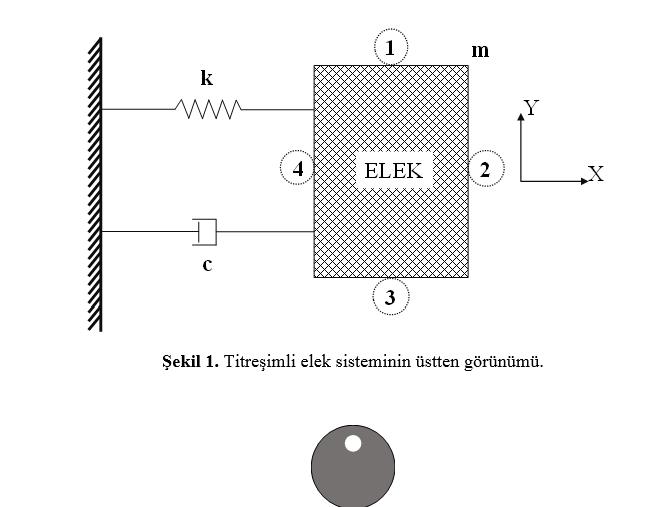
Step by Step Solution
3.32 Rating (161 Votes )
There are 3 Steps involved in it
1 N 1 m slt X X X N 1 11 N M 2x O ... View full answer

Get step-by-step solutions from verified subject matter experts