

Question: A well pump test is set up as shown in Figure 1 with the first observation well located at 5 0 feet ( r 1
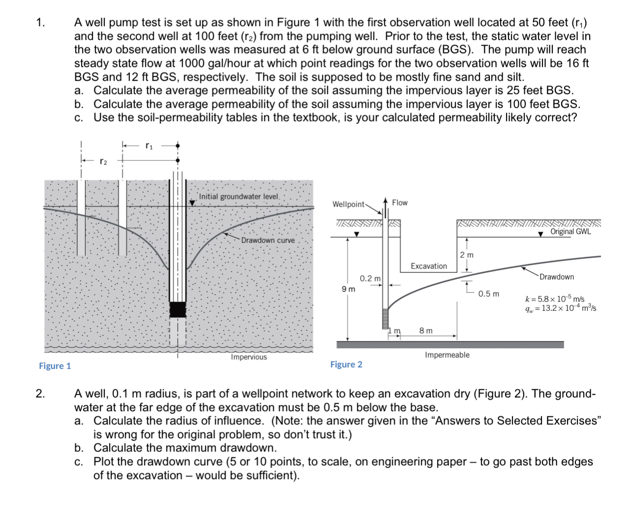
A well pump test is set up as shown in Figure with the first observation well located at feet and the second well at feet from the pumping well. Prior to the test, the static water level in the two observation wells was measured at below ground surface BGS The pump will reach steady state flow at our at which point readings for the two observation wells will be BGS and respectively. The soil is supposed to be mostly fine sand and silt.
a Calculate the average permeability of the soil assuming the impervious layer is feet BGS
b Calculate the average permeability of the soil assuming the impervious layer is feet BGS
c Use the soilpermeability tables in the textbook, is your calculated permeability likely correct?
A well, radius, is part of a wellpoint network to keep an excavation dry Figure The groundwater at the far edge of the excavation must be below the base.
a Calculate the radius of influence. Note: the answer given in the "Answers to Selected Exercises" is wrong for the original problem, so don't trust it
b Calculate the maximum drawdown.
c Plot the drawdown curve or points, to scale, on engineering paper to go past both edges of the excavation would be sufficient
Step by Step Solution
There are 3 Steps involved in it
1 Expert Approved Answer
Step: 1 Unlock

Question Has Been Solved by an Expert!
Get step-by-step solutions from verified subject matter experts
Step: 2 Unlock
Step: 3 Unlock