

Question: a2 Adash2 (1:3:end); * Filtering input data using three cascaded IIR sections yco filter (1, 0,x); $first 1st order section yei filter (1, al, yco);
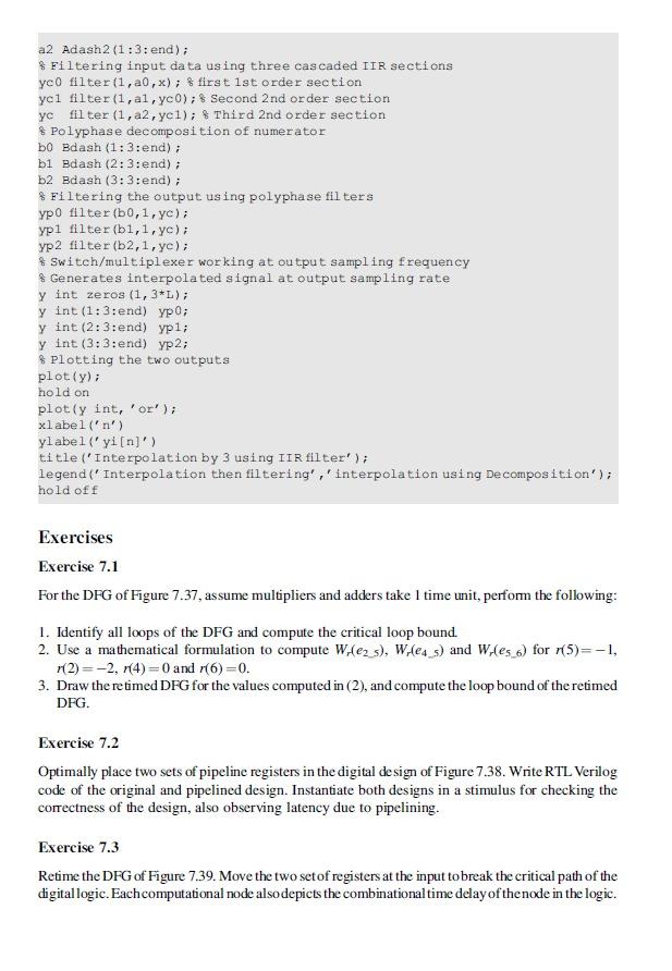
a2 Adash2 (1:3:end); * Filtering input data using three cascaded IIR sections yco filter (1, 0,x); $first 1st order section yei filter (1, al, yco); $ Second 2nd order section filter (1, 2, yel); $ Third 2nd order section % Polyphase decomposition of numerator bo Bdash (1:3:end); bi Bdash (2:3:end); b2 Bdash (3:3:end); & Filtering the output using polyphase filters ypo filter (60,1, yc); ypi filter (b1,1,y); yp2 filter (b2,1, ye); * Switch/multiplexer working at output sampling frequency $ Generates interpolated signal at output sampling rate y int zeros (1, 3*L); y int (1:3:end) yp0; y int (2:3:end) yp1; y int (3:3:end) yp2; Plotting the two outputs plot(y); hold on plot(y int, 'or' ); xlabel('n') ylabel('yi[n]') title('Interpolation by 3 using IIR filter' ); legend('Interpolation then filtering','interpolation using De composition'); hold off Exercises Exercise 7.1 For the DFG of Figure 7.37, assume multipliers and adders take 1 time unit, perform the following: 1. Identify all loops of the DFG and compute the critical loop bound. 2. Use a mathematical formulation to compute W.(62 s), Wiles_s) and W.Les_b) for (5)=-1, r(2)=-2, 7(4)=0 and (6)=0. 3. Draw the retimed DFG for the values computed in (2), and compute the loop bound of the retimed DFG. Exercise 7.2 Optimally place two sets of pipeline registers in the digital de sign of Figure 7.38. Write RTL Verilog code of the original and pipelined design. Instantiate both designs in a stimulus for checking the correctness of the design, also observing latency due to pipelining. Exercise 7.3 Retime the DFG of Figure 7.39. Move the two setof registers at the input to break the critical path of the digitallogic. Each computational node also depicts the combinationaltime delay of the node in the logic. a2 Adash2 (1:3:end); * Filtering input data using three cascaded IIR sections yco filter (1, 0,x); $first 1st order section yei filter (1, al, yco); $ Second 2nd order section filter (1, 2, yel); $ Third 2nd order section % Polyphase decomposition of numerator bo Bdash (1:3:end); bi Bdash (2:3:end); b2 Bdash (3:3:end); & Filtering the output using polyphase filters ypo filter (60,1, yc); ypi filter (b1,1,y); yp2 filter (b2,1, ye); * Switch/multiplexer working at output sampling frequency $ Generates interpolated signal at output sampling rate y int zeros (1, 3*L); y int (1:3:end) yp0; y int (2:3:end) yp1; y int (3:3:end) yp2; Plotting the two outputs plot(y); hold on plot(y int, 'or' ); xlabel('n') ylabel('yi[n]') title('Interpolation by 3 using IIR filter' ); legend('Interpolation then filtering','interpolation using De composition'); hold off Exercises Exercise 7.1 For the DFG of Figure 7.37, assume multipliers and adders take 1 time unit, perform the following: 1. Identify all loops of the DFG and compute the critical loop bound. 2. Use a mathematical formulation to compute W.(62 s), Wiles_s) and W.Les_b) for (5)=-1, r(2)=-2, 7(4)=0 and (6)=0. 3. Draw the retimed DFG for the values computed in (2), and compute the loop bound of the retimed DFG. Exercise 7.2 Optimally place two sets of pipeline registers in the digital de sign of Figure 7.38. Write RTL Verilog code of the original and pipelined design. Instantiate both designs in a stimulus for checking the correctness of the design, also observing latency due to pipelining. Exercise 7.3 Retime the DFG of Figure 7.39. Move the two setof registers at the input to break the critical path of the digitallogic. Each computational node also depicts the combinationaltime delay of the node in the logic
Step by Step Solution
There are 3 Steps involved in it

Get step-by-step solutions from verified subject matter experts