

Question: A2. Connect the circuit shown in the Fig. 9.2. This circuit uses a TTL type 74151 chip (8-to-1 MUX). Connect 12 binary switches to 8
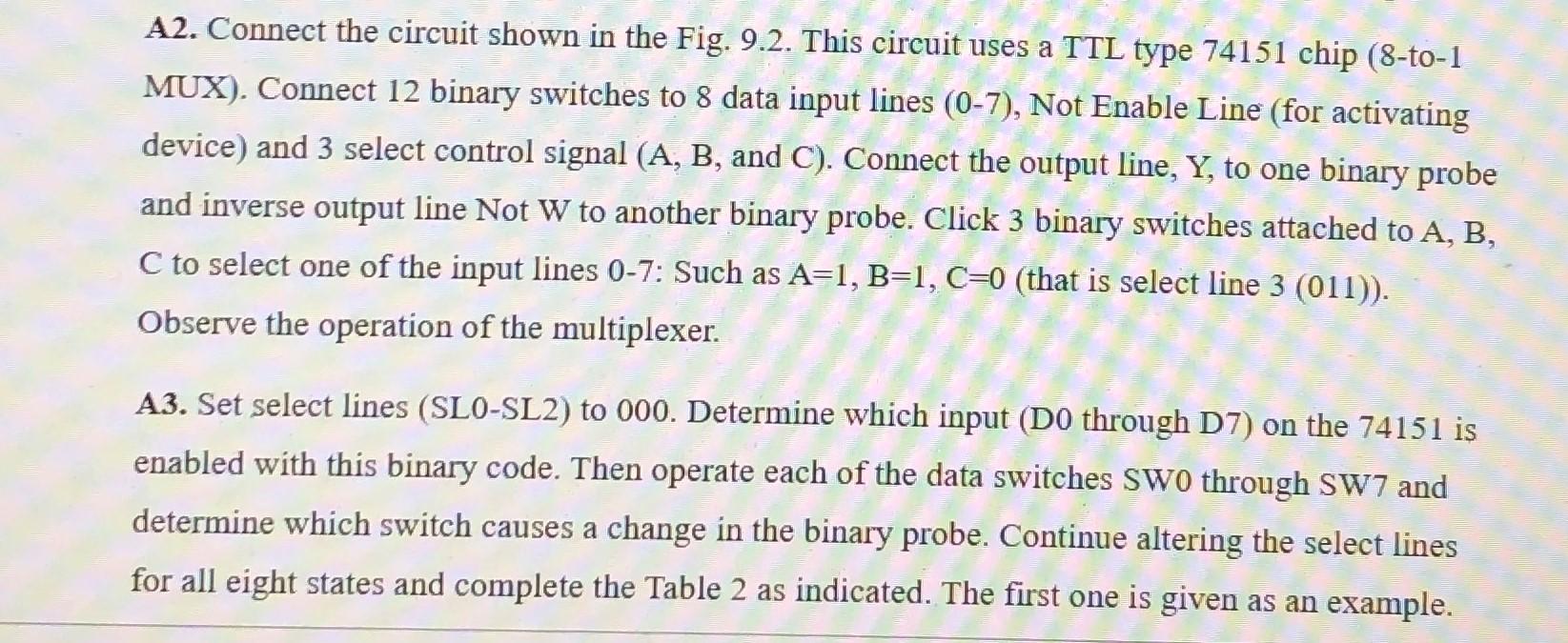
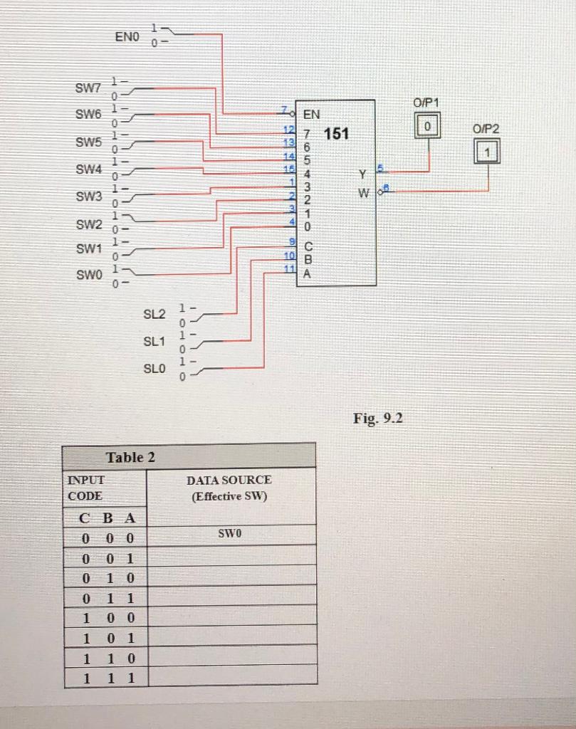


A2. Connect the circuit shown in the Fig. 9.2. This circuit uses a TTL type 74151 chip (8-to-1 MUX). Connect 12 binary switches to 8 data input lines (0-7), Not Enable Line (for activating device) and 3 select control signal (A, B, and C). Connect the output line, Y, to one binary probe and inverse output line Not W to another binary probe. Click 3 binary switches attached to A, B, C to select one of the input lines 0-7: Such as A=1, B=1, C=0 (that is select line 3 (011)). Observe the operation of the multiplexer. A3. Set select lines (SLO-SL2) to 000. Determine which input (D0 through D7) on the 74151 is enabled with this binary code. Then operate each of the data switches Swo through SW7 and determine which switch causes a change in the binary probe. Continue altering the select lines for all eight states and complete the Table 2 as indicated. The first one is given as an example. ENO SW7 1 O/P1 SW6 0 O/P2 SW5 1 SW4 EN 7 151 6 14 5 4 3 2 1 0 16 MOMONDO Y w lo SW3 SW2 SW1 1 SWO 0 SL2 SL1 OOO SLO Fig. 9.2 Table 2 INPUT CODE DATA SOURCE (Effective SW) CB A SWO 0 0 0 1 1 0 1 1 0 1 1 0 0 0 1 1 0 1 1 1 1 Q6. What is the function of E switch? EXERCISE Design a combinational circuit by using a 4x1 multiplexer (Mux-4 wo/EN) with three inputs A, B, C and one output Y. The output is one when binary value of the input is less than three. The output is zero otherwise. a Fill the truth table in table 3 for the given function and determine output Y in terms of C. Table 3 INPUTS OUTPUT A B Y 0 0 0 1 0 1 0 0 1 1 1 0 0 1 0 1 1 1 0 1 1 1 B. Design the circuit with a 4x1 multiplexer (if needed NOT gate can be used). DEZ c. Implement your design by Logic Works5. Verify the truth table obtained in part a and show your design to your instructor
Step by Step Solution
There are 3 Steps involved in it

Get step-by-step solutions from verified subject matter experts