

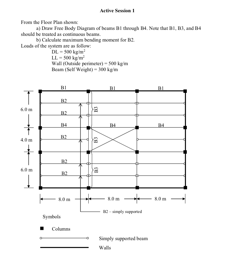
Question: Active Session 1 From the Floor Plan shown: a ) Draw Free Body Diagram of beams B 1 through B 4 . Note that B
Active Session
From the Floor Plan shown:
a Draw Free Body Diagram of beams B through B Note that B B and B should be treated as continuous beams.
b Calculate maximum bending moment for B
Loads of the system are as follow:
Wall perimeter
Beam Weight
Wall Outside perimeter
Beam Self Weight
Step by Step Solution
There are 3 Steps involved in it
1 Expert Approved Answer
Step: 1 Unlock

Question Has Been Solved by an Expert!
Get step-by-step solutions from verified subject matter experts
Step: 2 Unlock
Step: 3 Unlock