

Question: Activity 38-1-PLC Troubleshooting Operating and fault statts indicators incluce the power status, PC run, CPU fault, forced I/O, and battery-low indicators. The power status indicator
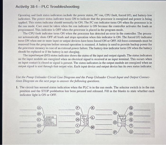
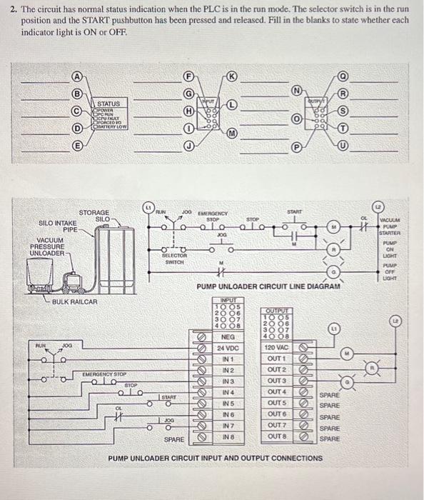
Activity 38-1-PLC Troubleshooting Operating and fault statts indicators incluce the power status, PC run, CPU fault, forced I/O, and battery-low indicators. The power status indicator tums ON to indicate that the processor is energized and power is being applied, This status indicator should normally be ON. The PC run indicator turns ON when the processor is in the num mode. Care must be takell when the nun indicator is ON because the controller activates the loads as programmed. This indicator is OFF when the processor is placed in the program mode. The CPU taull indicator turns ON when the processor has detected an error in the controller. The processor automatically shuts OFF all loads and stops operation when this indicator is ON. The forced I/O indicator tumis ON when one or more input or output devices have been forced ON or OFF. All force commands must be removed from the program before normal operation is resumed. A battery is used to provide backup power for the processor memory in case of an extemal power failure. The battery-low indicator turns ON when the battery should be replaced or if the baltery is not charging. The input/output (//O) status indicator shows the status of the input and output signals. The status indicators on the input module are energized when an elecirical signal is received at an input terminal. This occurs when an input contact is closed or signal is present. The status indicators in the output module are energized when an oulput signal is sent through that output wire. Each input device and output device has its own status indicator. Use the Pump Unloader Circuit Line Diagram and the Pump Unloader Circuit Input and Outpur Conneetions Diagram on the next page to answer the following questions. 1. The circuit has normal status indication when the PLC is in the run mode. The selector switch is in the run position and the STOP pushbutton has been pressed and relensed. Fill in the blanks to state whether each indicator light is ON or OFF. 2. The circuit has normal status indication when the PLC is in the run mode. The selector switch is in the run position and the START pushbutton has been pressed and released. Fill in the blanks to state whether each indicator light is ON or OFF. PUMP UNLOADER CIRCUIT INPUT AND OUTPUT CONNECTIONS
Step by Step Solution
There are 3 Steps involved in it

Get step-by-step solutions from verified subject matter experts