A.Determine the time constant of the L-R circuit shown in Fig. 1. B.The transient (adjustment) period of
Question:
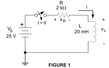
A.Determine the time constant of the L-R circuit shown in Fig. 1.
B.The transient (adjustment) period of the L-R circuit shown in Fig. 1 will essentially end in _____________.
C.The inductor used in the L-R circuit shown in Fig. 1 is initially unfluxed. The switch is closed at t = 0. What is the current through the circuit the instant after the switch is closed (t = 0+)?
D.The inductor used in the L-R circuit shown in Fig. 1 is initially unfluxed. The switch is closed at t = 0. What is the voltage across the resistor the instant after the switch is closed (t = 0+)?
E.The inductor used in the L-R circuit shown in Fig. 1 is initially unfluxed. The switch is closed at t = 0. What is the voltage across the inductor the instant after the switch is closed (t = 0+)?
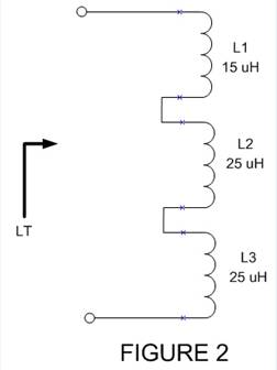
F.Compute the total inductance of the inductors shown in Fig. 2. There is no magnetic coupling (mutual inductance) between the coils.
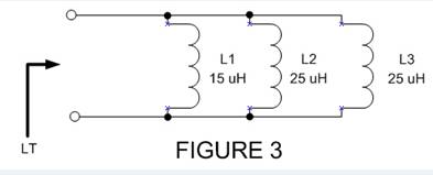
G. Compute the total inductance of the inductors shown in Fig. 3. There is no magnetic coupling (mutual inductance) between the coils.
Expert Answer: