Question: Advanced Heat Transfer - Performance Evaluation Criteria (PEC) for Single Phase Flow I am in need of assistance with solving the below advanced applied heat
Advanced Heat Transfer - Performance Evaluation Criteria (PEC) for Single Phase Flow I am in need of assistance with solving the below advanced applied heat transfer problem. When producing your results, please provide the following six elements (listed 1-6 below). Also, please ensure to include all units, conversions, and formulas used to formulate your answers. Thank you for the help. I'm completely stuck on this one :( (1) a brief summary of the problem statement
(2) a list of the knowns
(3) a list or brief description of what is to be solved or found
(4) a list of the assumptions that are necessary to solve the problem
(5) an analysis section that shows all work
(6) a conclusion section that summarizes the results
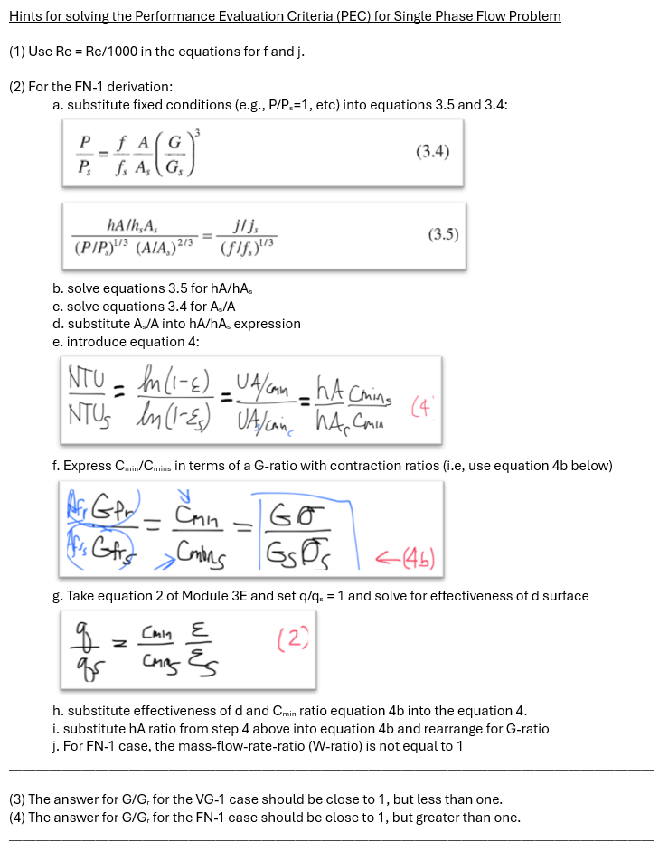
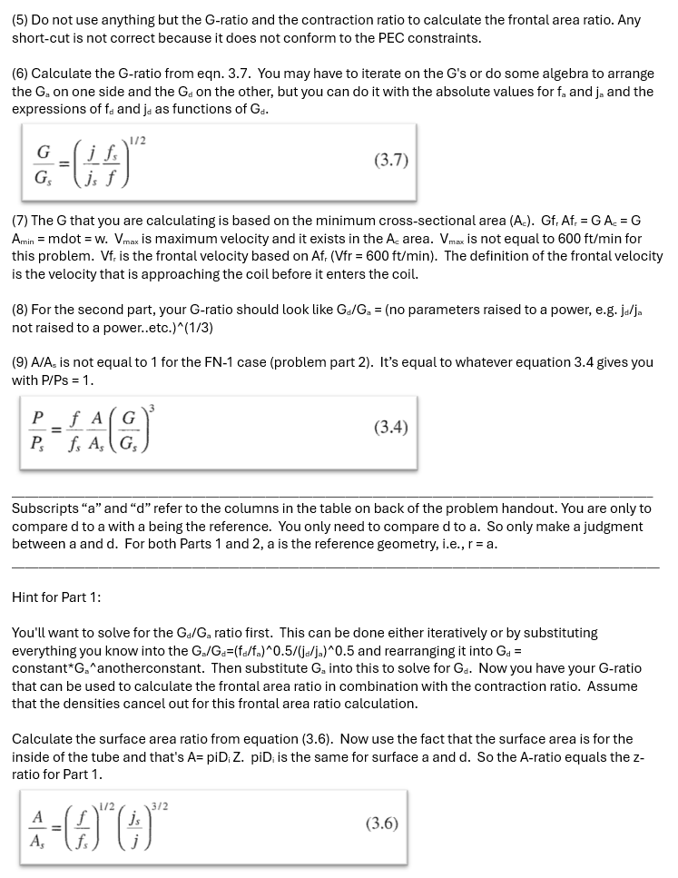
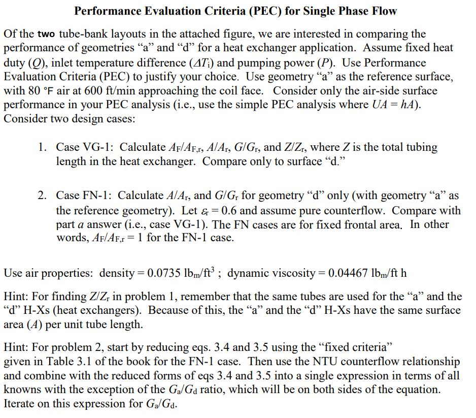
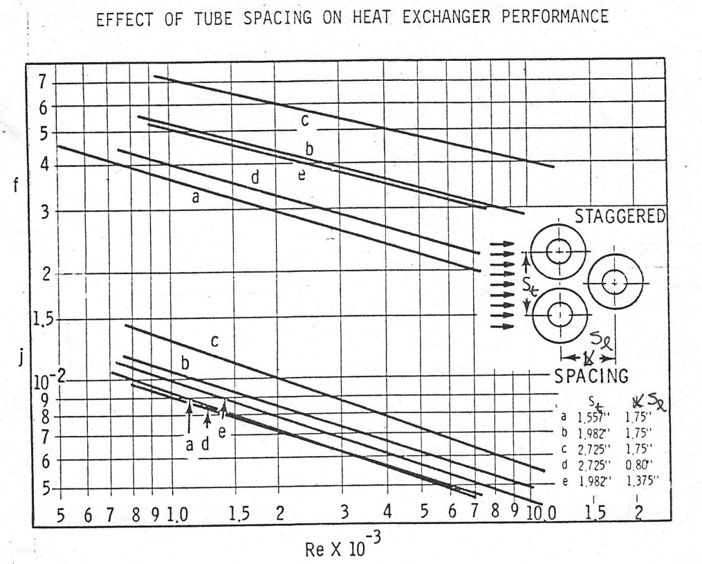
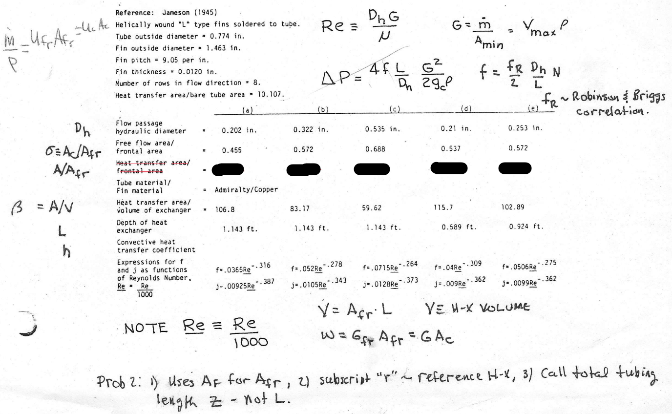
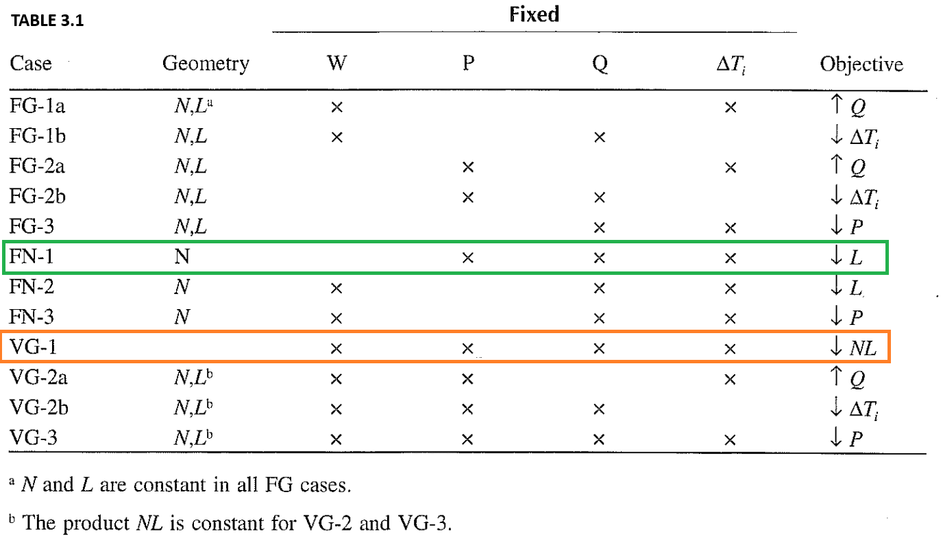
Hints for solving the Performance Evaluation Criteria (PEC) for Single Phase Flow Problem (1) Use Re = Re/1000 in the equations for f and j. (2) For the FN-1 derivation: a. substitute fixed conditions (e.g., P/P.=1, etc) into equations 3.5 and 3.4: PfAG (3.4) P, f, As G, hA/h,As ilis (3.5) (PIP,)1/3 (A/A,) 2/3 (fif,)13 b. solve equations 3.5 for hA/hAs c. solve equations 3.4 for A/A d. substitute A;/A into hA/hA expression e. introduce equation 4: NTU - In ( 1- E ) _ UA/ CAM - hA Cmins (4 NTUS In(1-Es ) UA/caine WA Cmin f. Express Cmin/Cmins in terms of a G-ratio with contraction ratios (i.e, use equation 4b below) = Can = GO GSDs 1- ( 46) g. Take equation 2 of Module 3E and set q/q. = 1 and solve for effectiveness of d surface CMin E (2 ) CMAS h. substitute effectiveness of d and Cmin ratio equation 4b into the equation 4. i. substitute hA ratio from step 4 above into equation 4b and rearrange for G-ratio j. For FN-1 case, the mass-flow-rate-ratio (W-ratio) is not equal to 1 (3) The answer for G/G, for the VG-1 case should be close to 1, but less than one. (4) The answer for G/G, for the FN-1 case should be close to 1, but greater than one.(5) Do not use anything but the G-ratio and the contraction ratio to calculate the frontal area ratio. Any short-cut is not correct because it does not conform to the PEC constraints. (6) Calculate the G-ratio from eqn. 3.7. You may have to iterate on the G's or do some algebra to arrange the G, on one side and the G, on the other, but you can do it with the absolute values for f, and j. and the expressions of f. and j. as functions of Gy. . 2 G -(4) (3.7) G, Is J (7) The G that you are calculating is based on the minimum cross-sectional area (A.). Gf, Af,=GA.=G Amin = mdot =wWw. Vinax iS Maximum velocity and it exists in the A. area. Vin. is not equal to 600 ft/min for this problem. Vi. is the frontal velocity based on Af, (Vir = 600 ft/min). The definition of the frontal velocity is the velocity that is approaching the coil before it enters the coil. (8) For the second part, your G-ratio should Look like G./G, = (no parameters raised to a power, @.g. ja/j. not raised to a power..etc.)*(1/3) (9) A/A. is not equal to 1 for the FN-1 case (problem part 2). It's equal to whatever equation 3.4 gives you with P/Ps = 1. pP_fA(Gy GA) Po fe As\\G; Subscripts \"a\" and \"d\" refer to the columns in the table on back of the problem handout. You are only to compare d to a with a being the reference. You only need to compare d to a. So only make a judgment between a and d. For both Parts 1 and 2, ais the reference geometry, i-e., r=a. Hint tor Part 1: You'll want to solve for the G,/G, ratio first. This can be done either iteratively or by substituting everything you know into the G./G,=(f./f.)0.5/(ja/j.)"0.5 and rearranging it into Gy = constant*G,*anotherconstant. Then substitute G, into this to solve for Gs. Now you have your G-ratio that can be used to calculate the frontal area ratio in combination with the contraction ratio. Assume that the densities cancel out for this frontal area ratio calculation. Calculate the surface area ratio from equation (3.6). Now use the fact that the surface area is for the inside of the tube and that's A= piD, 2. piD, is the same for surface a and d. So the A-ratio equals the z- ratio for Part 1. 4() (4) (3.6) A, \\f J Performance Evaluation Criteria (PEC) for Single Phase Flow Of the two tube-bank layouts in the attached figure, we are interested in comparing the performance of geometries "a" and "d" for a heat exchanger application. Assume fixed heat duty (Q), inlet temperature difference (471) and pumping power (P). Use Performance Evaluation Criteria (PEC) to justify your choice. Use geometry "a" as the reference surface, with 80 F air at 600 ft/min approaching the coil face. Consider only the air-side surface performance in your PEC analysis (i.e., use the simple PEC analysis where UA = hA). Consider two design cases: 1. Case VG-1: Calculate AF/AF,r, A/Ar, G/Gr, and Z/Zr, where Z is the total tubing length in the heat exchanger. Compare only to surface "d." 2. Case FN-1: Calculate A/Ar, and G/Gr for geometry "d" only (with geometry "a" as the reference geometry). Let & = 0.6 and assume pure counterflow. Compare with part a answer (i.e., case VG-1). The FN cases are for fixed frontal area. In other words, AF/AF,r = 1 for the FN-1 case. Use air properties: density = 0.0735 1bm/ft' ; dynamic viscosity = 0.04467 1bm/ft h Hint: For finding Z/Zr in problem 1, remember that the same tubes are used for the "a" and the 'd" H-Xs (heat exchangers). Because of this, the "a" and the "d" H-Xs have the same surface area (A) per unit tube length. Hint: For problem 2, start by reducing eqs. 3.4 and 3.5 using the "fixed criteria" given in Table 3.1 of the book for the FN-1 case. Then use the NTU counterflow relationship and combine with the reduced forms of eqs 3.4 and 3.5 into a single expression in terms of all knowns with the exception of the Ga/Ga ratio, which will be on both sides of the equation. Iterate on this expression for Ga/Ga.EFFECT OF TUBE SPACING ON HEAT EXCHANGER PERFORMANCE C A VIA d e a W STAGGERED 2 15 C b -2. SPACING SE a 1.557" 1.75" Ula NOOO ad b 1.982"' 1.75" C 2.725" 1.75" d 2.725" 0.80' e 1.982" 1,375" 5 6 7 8 910 1.5 2 3 4 5 6 7 8 9 10 0 15 2 Re X 10 3Reference: Jameson (1945) Uc Ac Helically wound "L" type fins soldered to tube. Re = DIG i _ufpAFS P Tube outside diameter = 0.774 in. N G = m = max Fin outside diameter = 1. 463 in. Amin P Fin pitch = 9.05 per in. Fin thickness = 0.0120 in. AP= 4fL 62 f = FR Dh N Number of rows in flow direction = 8. On 29P 2 I Heat transfer area/bare tube area = 10. 107. (e FR~ Robinson & Briggs (a ) (b) (c) (d) correlation . Dh Flow passage hydraulic diameter 0. 202 in. 0. 322 in. 0.535 in. 0.21 in. 0. 253 in. Free flow area/ O=AC/Afr frontal area 0. 455 0.572 0. 688 0.537 0. 572 Heat transfer area/ A/Afr frontal area Tube material/ Fin material Admiralty/Copper B = A /V Heat transfer area/ volume of exchanger - 106.8 83. 17 59. 62 115.7 102. 89 Depth of heat L exchanger 1. 143 ft. 1. 143 ft. 1. 143 ft. 0. 589 ft. 0. 924 ft. Convection heat hi transfer coefficient Expressions for f and j as functions f= . 0365Re " . 316 f= . 052Re -. 278 f= . 0715Re - . 264 f= . 04Re" . 309 f= . 0506Re" . 275 of Reynolds Number. Re . Re J- . 00925Re - . 387 j= . 0105Re" - . 343 j= . 0128Re " . 373 j= . 009Re A " . 362 J= . 0099Re " . 362 1000 Y = Afr. L YE H-X VOLUME NOTE Re = Re 1000 W = GSP Afr = GAc Prob 2: 1) Uses AF for Afr, 21 subscript "r" ~ reference H-X, 3/ Call total tubing length Z - not L.TABLE 3.1 Fixed Case Geometry W P Q AT; Objective FG-la X X TO FG-1b N.L X X FG-2a N.L X X TO FG-2b N.L X X LAT FG-3 N.L X X FN-1 N X X X FN-2 N X X X FN-3 N X X X I P VG-1 X X X X _ NL VG-2a N,Lb X X X VG-2b N.Lb X X X & AT VG-3 N.Lb X X X X a N and L are constant in all FG cases. The product NL is constant for VG-2 and VG-3
Step by Step Solution
There are 3 Steps involved in it
1 Expert Approved Answer
Step: 1 Unlock
Question Has Been Solved by an Expert!
Get step-by-step solutions from verified subject matter experts
Step: 2 Unlock
Step: 3 Unlock
Students Have Also Explored These Related Accounting Questions!