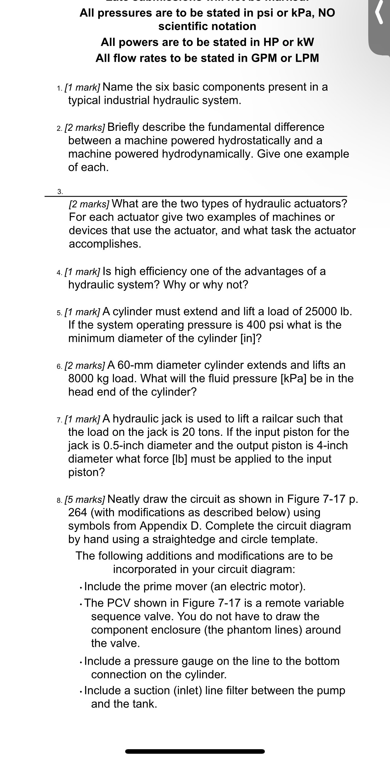
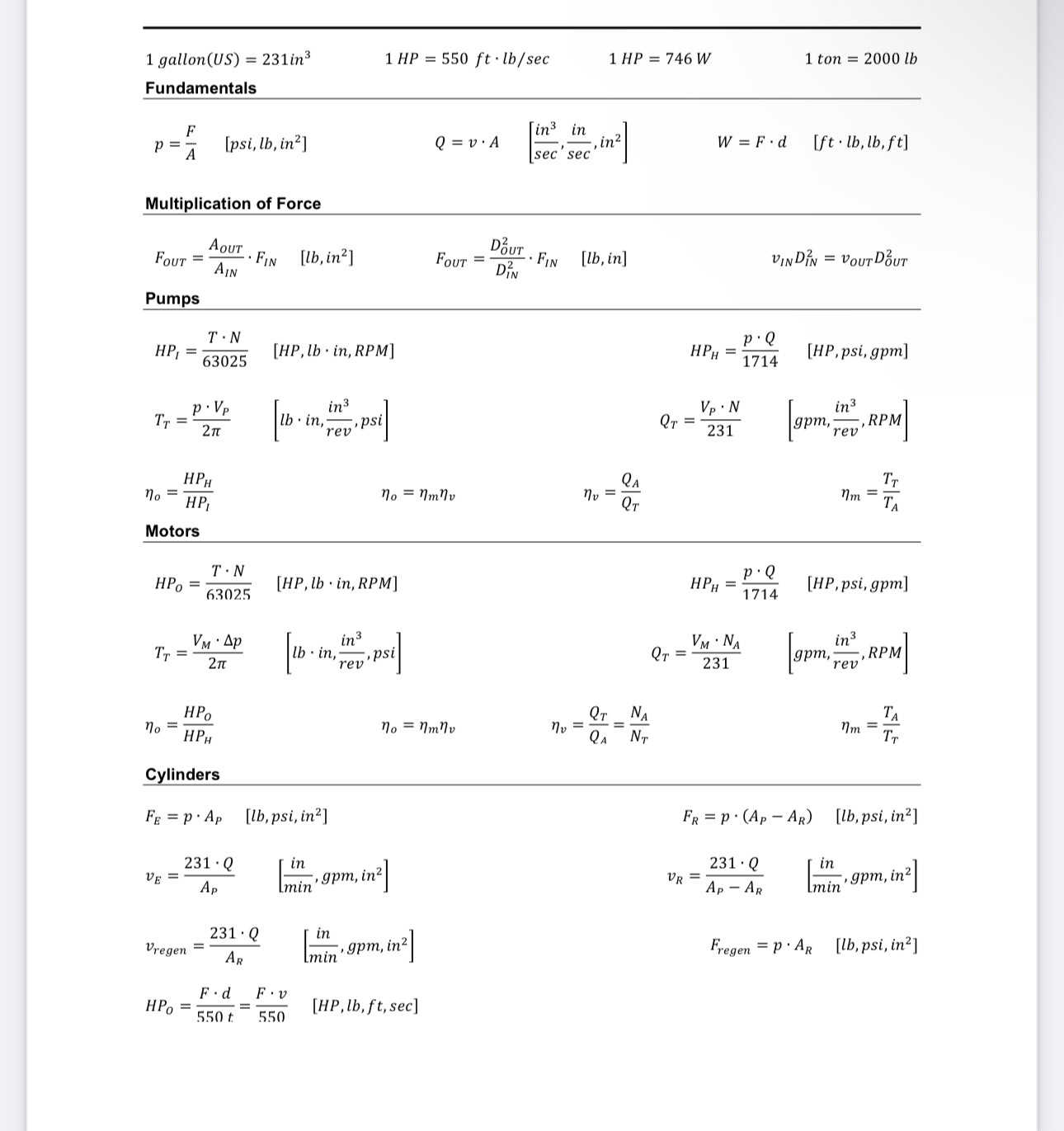
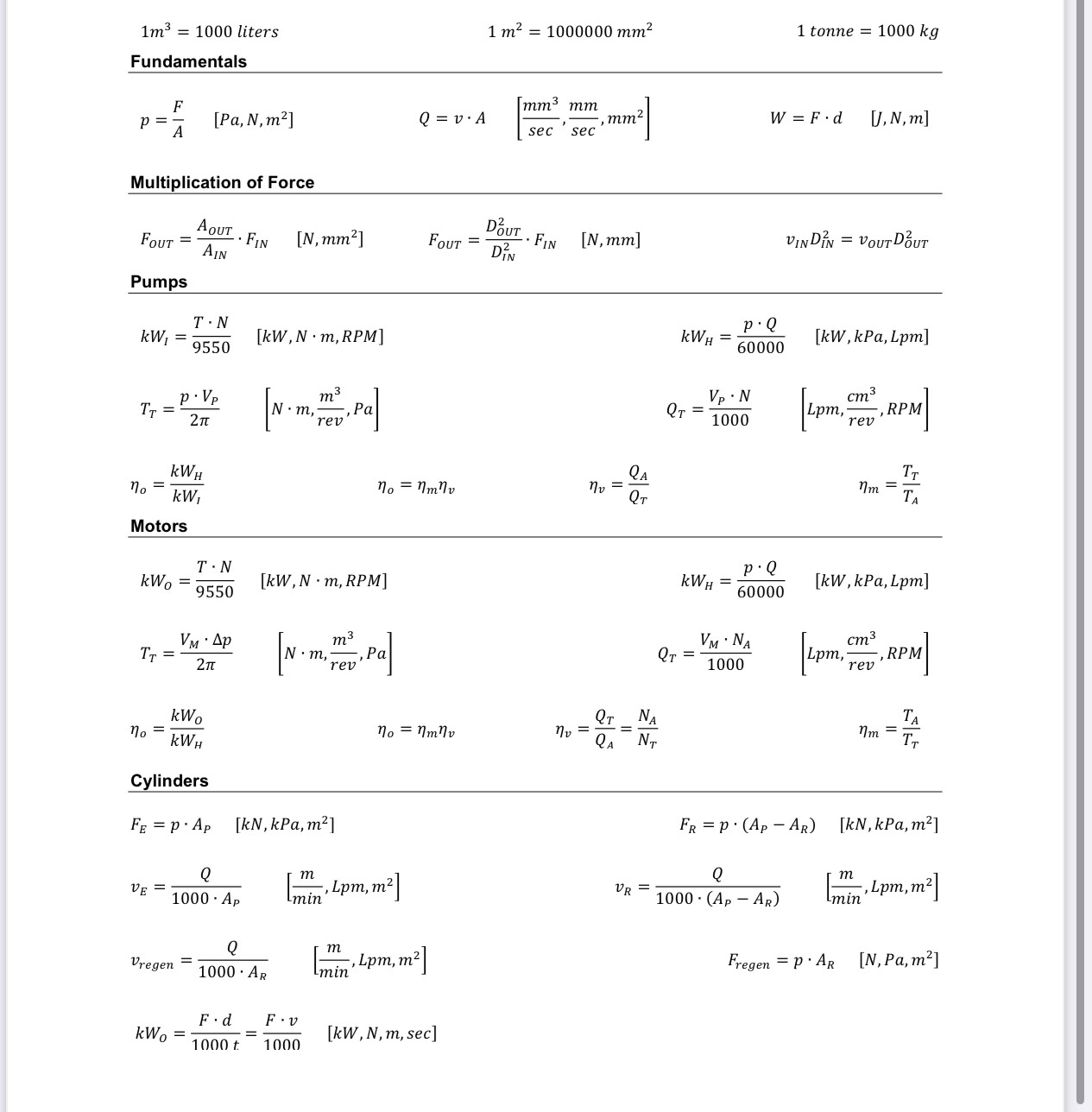
All pressures are to be stated in psi or kPa, NO scientific notation All powers are...
Fantastic news! We've Found the answer you've been seeking!
Question:
![image text in transcribed](https://s3.amazonaws.com/si.experts.images/answers/2024/05/6648454709b4e_35866484546d36b6.jpg)
![image text in transcribed](https://s3.amazonaws.com/si.experts.images/answers/2024/05/6648454781c5a_359664845475ce73.jpg)
![image text in transcribed](https://s3.amazonaws.com/si.experts.images/answers/2024/05/66484547ddcf5_35966484547c1195.jpg)
Transcribed Image Text:
All pressures are to be stated in psi or kPa, NO scientific notation All powers are to be stated in HP or kW All flow rates to be stated in GPM or LPM 1. [1 mark] Name the six basic components present in a typical industrial hydraulic system. 2. [2 marks] Briefly describe the fundamental difference between a machine powered hydrostatically and a machine powered hydrodynamically. Give one example of each. 3. [2 marks] What are the two types of hydraulic actuators? For each actuator give two examples of machines or devices that use the actuator, and what task the actuator accomplishes. 4. [1 mark] Is high efficiency one of the advantages of a hydraulic system? Why or why not? 5. [1 mark] A cylinder must extend and lift a load of 25000 lb. If the system operating pressure is 400 psi what is the minimum diameter of the cylinder [in]? 6. [2 marks] A 60-mm diameter cylinder extends and lifts an 8000 kg load. What will the fluid pressure [kPa] be in the head end of the cylinder? 7. [1 mark] A hydraulic jack is used to lift a railcar such that the load on the jack is 20 tons. If the input piston for the jack is 0.5-inch diameter and the output piston is 4-inch diameter what force [lb] must be applied to the input piston? 8. [5 marks] Neatly draw the circuit as shown in Figure 7-17 p. 264 (with modifications as described below) using symbols from Appendix D. Complete the circuit diagram by hand using a straightedge and circle template. The following additions and modifications are to be incorporated in your circuit diagram: . Include the prime mover (an electric motor). .The PCV shown in Figure 7-17 is a remote variable sequence valve. You do not have to draw the component enclosure (the phantom lines) around the valve. . Include a pressure gauge on the line to the bottom connection on the cylinder. Include a suction (inlet) line filter between the pump and the tank. 1 gallon (US) 231in 1 HP 550 ft lb/sec 1 HP 746 W 1 ton 2000 lb Fundamentals F [in3 in P = A [psi, lb, in] Q = v A in W = F.d [ft. lb, lb, ft] sec sec Multiplication of Force AOUT FOUT = FIN [lb, in] DOUT FOUT = FIN [lb, in] VINDIN = VOUT DUT AIN DN Pumps T N HP = [HP, lb. in, RPM] HPH P.Q = [HP, psi, gpm] 63025 1714 P.Vp in TT = lb lb in, psi 2 revi Vp. N 231 in [gpm.. RPM] rev HPH no = HP Motors HPO = T N 63025 No = nmnv QT [HP, lb in, RPM] VM Ap in TT = lb in, 2 psi rev TT nm = TA HPH = P.Q 1714 [HP, psi, gpm] QT = VM. NA 231 in gpm, rev' RPM] NA QA = NT Nm = TT No = nmnv nv = 22 QT HPO no HPH Cylinders FE = p. Ap [lb, psi, in] 231 Q VE = in Lmin gpm, in in] Vregen 231 Q AR in gpm, in2 [min n] F.d = 550 t F.v 550 [HP, lb, ft, sec] FR p (Ap AR) [lb, psi, in] VR = 231 Q AP-AR in gpm, in2 [min Fregen = p. AR [lb, psi, in] 1m 1000 liters Fundamentals 1 m 1000000 mm 1 tonne 1000 kg F p = [Pa, N, m] mm mm Q = v. A A , mm W = F.d sec sec [J, N, m] Multiplication of Force AOUT DUT FOUT = FIN [N, mm] FOUT = FIN [N, mm] VINDIN =VOUT DOUT AIN DN Pumps T N kW = [kW, N m, RPM] 9550 p. Vp TT = Nm, , Pa 2 3 m rev KWH no = kW, Motors T N kWo 9550 No = nmnv nv = 35 QA p.Q KWH = [kW, kPa, Lpm] 60000 VP.N 1000 cm Lpm, -, RPM rev TT Nm = [kW, N m, RPM] VM. Ap TT = 2 [N m Nm, ,Pa rev kWo No = KWH Cylinders QT No = nmnv nv = QA NT FE = p. Ap [kN, kPa, m] Q m VE Lpm, m m] 1000. Ap Imin Q m Vregen = , Lpm, m 1000 AR Imin F.d kW = 1000 t F. v 1000 [kW, N, m, sec] p.Q KWH = [kW, kPa, Lpm] 60000 QT = VM. NA 1000 cm Lpm, rev .RPM] TA Nm = TT FR p (Ap AR) [kN, kPa, m] VR Q 1000 (Ap AR) m -, Lpm, m n] Imin Fregen = p. AR [N, Pa,m] All pressures are to be stated in psi or kPa, NO scientific notation All powers are to be stated in HP or kW All flow rates to be stated in GPM or LPM 1. [1 mark] Name the six basic components present in a typical industrial hydraulic system. 2. [2 marks] Briefly describe the fundamental difference between a machine powered hydrostatically and a machine powered hydrodynamically. Give one example of each. 3. [2 marks] What are the two types of hydraulic actuators? For each actuator give two examples of machines or devices that use the actuator, and what task the actuator accomplishes. 4. [1 mark] Is high efficiency one of the advantages of a hydraulic system? Why or why not? 5. [1 mark] A cylinder must extend and lift a load of 25000 lb. If the system operating pressure is 400 psi what is the minimum diameter of the cylinder [in]? 6. [2 marks] A 60-mm diameter cylinder extends and lifts an 8000 kg load. What will the fluid pressure [kPa] be in the head end of the cylinder? 7. [1 mark] A hydraulic jack is used to lift a railcar such that the load on the jack is 20 tons. If the input piston for the jack is 0.5-inch diameter and the output piston is 4-inch diameter what force [lb] must be applied to the input piston? 8. [5 marks] Neatly draw the circuit as shown in Figure 7-17 p. 264 (with modifications as described below) using symbols from Appendix D. Complete the circuit diagram by hand using a straightedge and circle template. The following additions and modifications are to be incorporated in your circuit diagram: . Include the prime mover (an electric motor). .The PCV shown in Figure 7-17 is a remote variable sequence valve. You do not have to draw the component enclosure (the phantom lines) around the valve. . Include a pressure gauge on the line to the bottom connection on the cylinder. Include a suction (inlet) line filter between the pump and the tank. 1 gallon (US) 231in 1 HP 550 ft lb/sec 1 HP 746 W 1 ton 2000 lb Fundamentals F [in3 in P = A [psi, lb, in] Q = v A in W = F.d [ft. lb, lb, ft] sec sec Multiplication of Force AOUT FOUT = FIN [lb, in] DOUT FOUT = FIN [lb, in] VINDIN = VOUT DUT AIN DN Pumps T N HP = [HP, lb. in, RPM] HPH P.Q = [HP, psi, gpm] 63025 1714 P.Vp in TT = lb lb in, psi 2 revi Vp. N 231 in [gpm.. RPM] rev HPH no = HP Motors HPO = T N 63025 No = nmnv QT [HP, lb in, RPM] VM Ap in TT = lb in, 2 psi rev TT nm = TA HPH = P.Q 1714 [HP, psi, gpm] QT = VM. NA 231 in gpm, rev' RPM] NA QA = NT Nm = TT No = nmnv nv = 22 QT HPO no HPH Cylinders FE = p. Ap [lb, psi, in] 231 Q VE = in Lmin gpm, in in] Vregen 231 Q AR in gpm, in2 [min n] F.d = 550 t F.v 550 [HP, lb, ft, sec] FR p (Ap AR) [lb, psi, in] VR = 231 Q AP-AR in gpm, in2 [min Fregen = p. AR [lb, psi, in] 1m 1000 liters Fundamentals 1 m 1000000 mm 1 tonne 1000 kg F p = [Pa, N, m] mm mm Q = v. A A , mm W = F.d sec sec [J, N, m] Multiplication of Force AOUT DUT FOUT = FIN [N, mm] FOUT = FIN [N, mm] VINDIN =VOUT DOUT AIN DN Pumps T N kW = [kW, N m, RPM] 9550 p. Vp TT = Nm, , Pa 2 3 m rev KWH no = kW, Motors T N kWo 9550 No = nmnv nv = 35 QA p.Q KWH = [kW, kPa, Lpm] 60000 VP.N 1000 cm Lpm, -, RPM rev TT Nm = [kW, N m, RPM] VM. Ap TT = 2 [N m Nm, ,Pa rev kWo No = KWH Cylinders QT No = nmnv nv = QA NT FE = p. Ap [kN, kPa, m] Q m VE Lpm, m m] 1000. Ap Imin Q m Vregen = , Lpm, m 1000 AR Imin F.d kW = 1000 t F. v 1000 [kW, N, m, sec] p.Q KWH = [kW, kPa, Lpm] 60000 QT = VM. NA 1000 cm Lpm, rev .RPM] TA Nm = TT FR p (Ap AR) [kN, kPa, m] VR Q 1000 (Ap AR) m -, Lpm, m n] Imin Fregen = p. AR [N, Pa,m]
Expert Answer:
Posted Date:
![Mobile App Logo](https://dsd5zvtm8ll6.cloudfront.net/includes/images/mobile/finalLogo.png)
Study smarter with the SolutionInn App