

Question: All the codes are written in 8086 assembly code 3) The following questions are set up in view of the Figures (d,e) a) Describe what
All the codes are written in 8086 assembly code
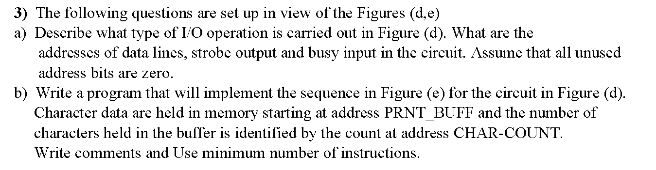
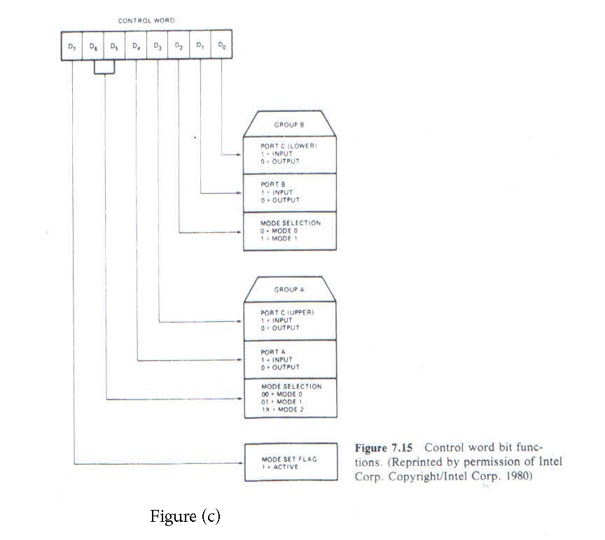
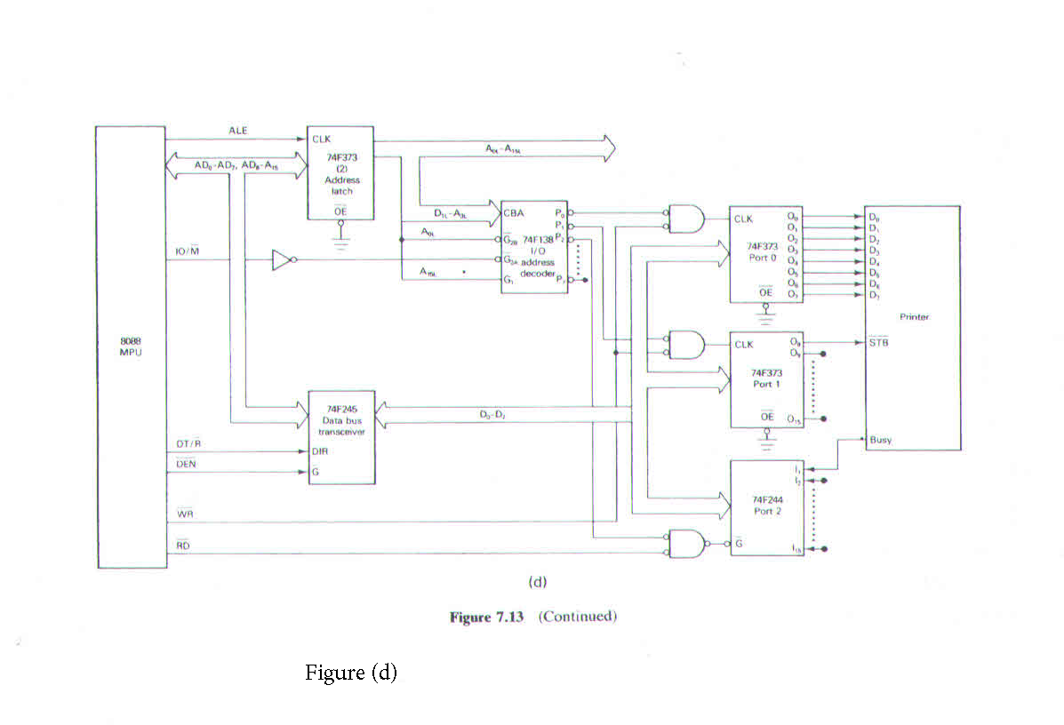
3) The following questions are set up in view of the Figures (d,e) a) Describe what type of I/O operation is carried out in Figure (d). What are the addresses of data lines, strobe output and busy input in the circuit. Assume that all unused address bits are zero. b) Write a program that will implement the sequence in Figure (e) for the circuit in Figure (d). Character data are held in memory starting at address PRNT_BUFF and the number of characters held in the buffer is identified by the count at address CHAR-COUNT. Write comments and Use minimum number of instructions. CONTROL WORD 0 0.0 0.0 0. o De GROUP PORT CLOWER 1- INPUT 0 OUTPUT POATS INPUT 0. OUTPUT MODE SELECTION D. MODE O MODE1 GROUP A PORT CIUPPERS 1 INPUT 0. OUTPUT PORTA 1 INPUT 0 - OUTPUT MODE SELECTION 00 MODE O 01 MODE 1X MODE MODE SET FLAG 1 ACTIVE Figure 7.15 Control word bit func- tions (Reprinted by permission of Intel Corp. Copyright/Intel Corp. 1980) Figure (c) ALE CLK Au As AD, AD, AD, A 74F373 (2) Address latch OL D-A CLK A CBA P. 7 Pb do 24F138 10 D D D D) D 0 74F373 0 Port 0 . 10/M dos address decoder A G O OE D D Printer 8088 MPU CLK 0, STB 74F373 Part 1 0,- 74F245 Data bus transceiver OE 0 OT/R Busy DIR DEN G 74F244 Port 2 WA RD (d) Figure 7.13 (Continued) Figure (d) 3) The following questions are set up in view of the Figures (d,e) a) Describe what type of I/O operation is carried out in Figure (d). What are the addresses of data lines, strobe output and busy input in the circuit. Assume that all unused address bits are zero. b) Write a program that will implement the sequence in Figure (e) for the circuit in Figure (d). Character data are held in memory starting at address PRNT_BUFF and the number of characters held in the buffer is identified by the count at address CHAR-COUNT. Write comments and Use minimum number of instructions. CONTROL WORD 0 0.0 0.0 0. o De GROUP PORT CLOWER 1- INPUT 0 OUTPUT POATS INPUT 0. OUTPUT MODE SELECTION D. MODE O MODE1 GROUP A PORT CIUPPERS 1 INPUT 0. OUTPUT PORTA 1 INPUT 0 - OUTPUT MODE SELECTION 00 MODE O 01 MODE 1X MODE MODE SET FLAG 1 ACTIVE Figure 7.15 Control word bit func- tions (Reprinted by permission of Intel Corp. Copyright/Intel Corp. 1980) Figure (c) ALE CLK Au As AD, AD, AD, A 74F373 (2) Address latch OL D-A CLK A CBA P. 7 Pb do 24F138 10 D D D D) D 0 74F373 0 Port 0 . 10/M dos address decoder A G O OE D D Printer 8088 MPU CLK 0, STB 74F373 Part 1 0,- 74F245 Data bus transceiver OE 0 OT/R Busy DIR DEN G 74F244 Port 2 WA RD (d) Figure 7.13 (Continued) Figure (d)
Step by Step Solution
There are 3 Steps involved in it

Get step-by-step solutions from verified subject matter experts