

Question: An intelligent system for regulating the force produced by a mechanical system is presented in Figure 1. An input voltage Um drives the system, and
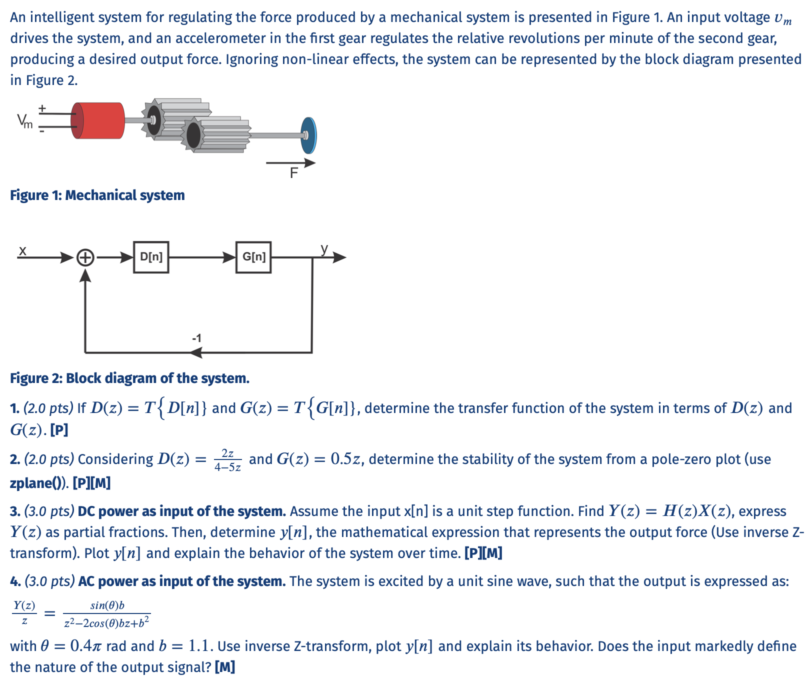
An intelligent system for regulating the force produced by a mechanical system is presented in Figure 1. An input voltage Um drives the system, and an accelerometer in the first gear regulates the relative revolutions per minute of the second gear, producing a desired output force. Ignoring non-linear effects, the system can be represented by the block diagram presented in Figure 2. + Vm Figure 1: Mechanical system D[n] G[n] -1 2z 4-5z Figure 2: Block diagram of the system. 1. (2.0 pts) If D(z) = T{D[n]} and G(z) = T{G[n]}, determine the transfer function of the system in terms of D(z) and G(z). [P] 2. (2.0 pts) Considering D(z) = and G(z) = 0.5z, determine the stability of the system from a pole-zero plot (use zplane()). [P][M] 3. (3.0 pts) DC power as input of the system. Assume the input x[n] is a unit step function. Find Y(z) = H(z)X(z), express Y(z) as partial fractions. Then, determine y[n], the mathematical expression that represents the output force (Use inverse Z- transform). Plot y[n] and explain the behavior of the system over time. [P][M] 4. (3.0 pts) AC power as input of the system. The system is excited by a unit sine wave, such that the output is expressed as: Y(z) sin(0) 222cos(0)bz+62 with 0 = 0.41 rad and b = 1.1. Use inverse Z-transform, plot y[n] and explain its behavior. Does the input markedly define the nature of the output signal? [M] z An intelligent system for regulating the force produced by a mechanical system is presented in Figure 1. An input voltage Um drives the system, and an accelerometer in the first gear regulates the relative revolutions per minute of the second gear, producing a desired output force. Ignoring non-linear effects, the system can be represented by the block diagram presented in Figure 2. + Vm Figure 1: Mechanical system D[n] G[n] -1 2z 4-5z Figure 2: Block diagram of the system. 1. (2.0 pts) If D(z) = T{D[n]} and G(z) = T{G[n]}, determine the transfer function of the system in terms of D(z) and G(z). [P] 2. (2.0 pts) Considering D(z) = and G(z) = 0.5z, determine the stability of the system from a pole-zero plot (use zplane()). [P][M] 3. (3.0 pts) DC power as input of the system. Assume the input x[n] is a unit step function. Find Y(z) = H(z)X(z), express Y(z) as partial fractions. Then, determine y[n], the mathematical expression that represents the output force (Use inverse Z- transform). Plot y[n] and explain the behavior of the system over time. [P][M] 4. (3.0 pts) AC power as input of the system. The system is excited by a unit sine wave, such that the output is expressed as: Y(z) sin(0) 222cos(0)bz+62 with 0 = 0.41 rad and b = 1.1. Use inverse Z-transform, plot y[n] and explain its behavior. Does the input markedly define the nature of the output signal? [M] z
Step by Step Solution
There are 3 Steps involved in it

Get step-by-step solutions from verified subject matter experts