

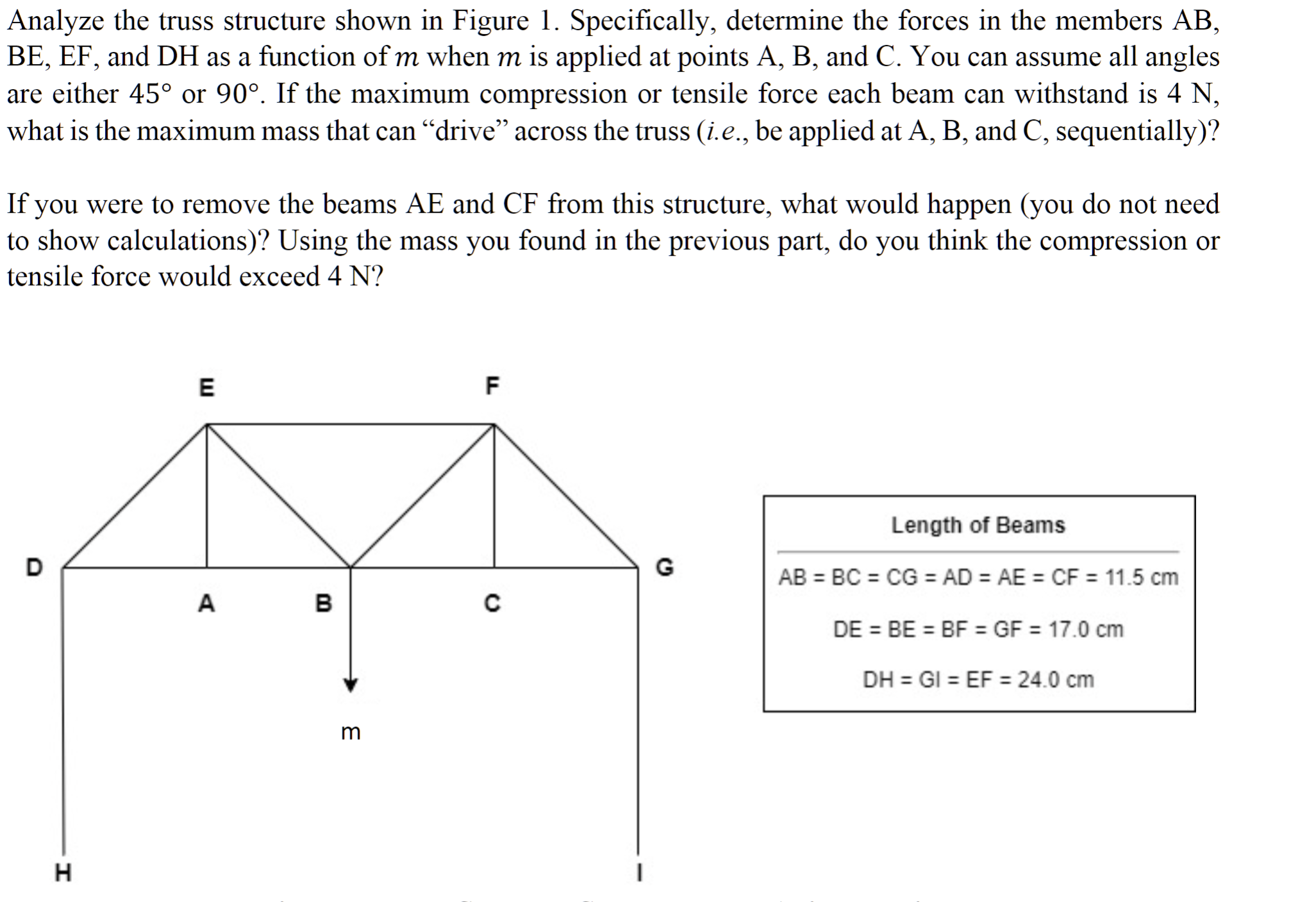
Question: Analyze the truss structure shown in Figure 1 . Specifically, determine the forces in the members A B , B E , E F ,
Analyze the truss structure shown in Figure Specifically, determine the forces in the members
and as a function of when is applied at points and You can assume all angles
are either or If the maximum compression or tensile force each beam can withstand is
what is the maximum mass that can "drive" across the truss ie be applied at A B and C sequentially
If you were to remove the beams and from this structure, what would happen you do not need
to show calculations Using the mass you found in the previous part, do you think the compression or
tensile force would exceed
Length Beams
Step by Step Solution
There are 3 Steps involved in it
1 Expert Approved Answer
Step: 1 Unlock

Question Has Been Solved by an Expert!
Get step-by-step solutions from verified subject matter experts
Step: 2 Unlock
Step: 3 Unlock