

Question: analyzed the torque required on the OA bar for the mechanism to move with constant of 2 0 rpm , rotating the bar OA uniformly
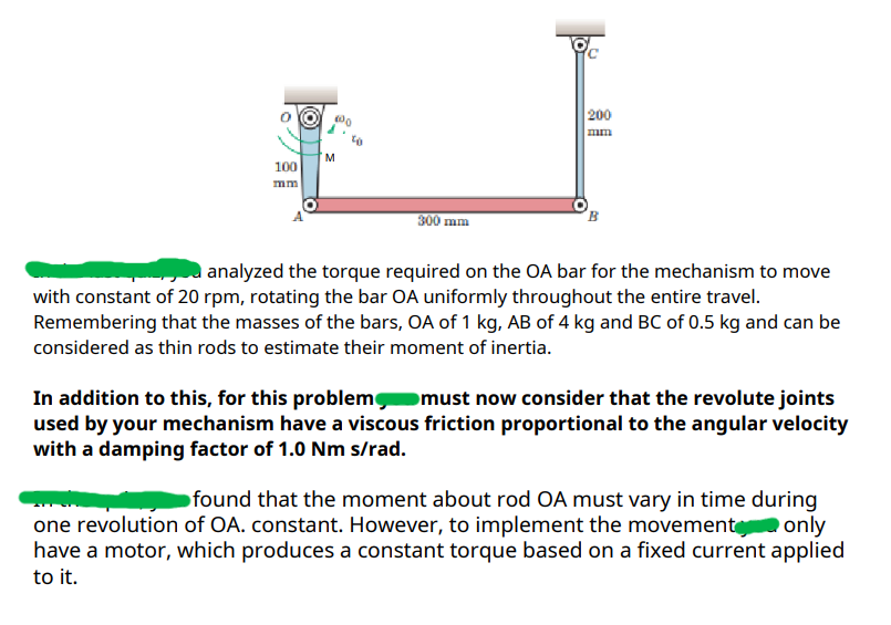
analyzed the torque required on the OA bar for the mechanism to move with constant of rpm rotating the bar OA uniformly throughout the entire travel. Remembering that the masses of the bars, O A of mathrm~kg A B of kg and B C of kg and can be considered as thin rods to estimate their moment of inertia.
In addition to this, for this problem must now consider that the revolute joints used by your mechanism have a viscous friction proportional to the angular velocity with a damping factor of Nm srad
found that the moment about rod OA must vary in time during one revolution of OA constant. However, to implement the movement, only have a motor, which produces a constant torque based on a fixed current applied to it The objective is to design a flywheel that is rigidly connected to OA and allows speed to be maintained. at its nominal value of rpm with maximum variations of That is it cannot exceed rpm or move below rpm To solve this problem, perform the following recommended process:
A For reference, perform an inverse dynamics analysis andgraph the ideal moment that a motor should make during one revolution of the mechanism so that OA moves at constant speedan M vs time graph In this same graph include a dotted line that shows the average value of the Moment Mavg
B Perform a forward dynamics analysis starting from the initial condition and with a constant input of Momentum in OAPlot the angular velocity of OA during some motion cycles of the mechanism for the input moment cases: Mavg Mavg Mavg, Mavg Mavg in this same graph include a dotted line that shows the value of the desired nominal speed.
C Analyzing the results from point B select a reasonable value for the constant input moment at OA Using this value as the constant input Moment at OA perform a forward dynamics analysis starting from the initial condition and modifying the value of the inertia of OA Plot the angular velocity of OA over a few motion cycles for the Inertia cases x x x x In this same graph, include dotted lines that show the value of the nominal speed and its maximum and minimum values allowed.
Step by Step Solution
There are 3 Steps involved in it
1 Expert Approved Answer
Step: 1 Unlock

Question Has Been Solved by an Expert!
Get step-by-step solutions from verified subject matter experts
Step: 2 Unlock
Step: 3 Unlock