

Question: answer all 4 cases please. MATERIALS CLICK PLC OBJECTIVE Introduce PLC programming and explore the basic function of the CLICK software and switches and counters
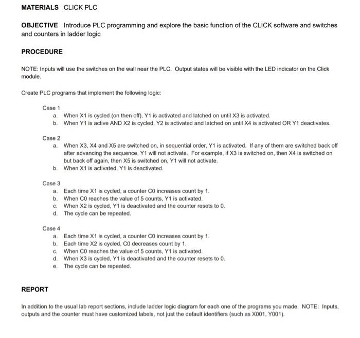
MATERIALS CLICK PLC OBJECTIVE Introduce PLC programming and explore the basic function of the CLICK software and switches and counters in ladder logic PROCEDURE NOTE: Inputs will use the switches on the wall near the PLC. Output states will be visible with the LED indicator on the Click module Create PLC programs that implement the following logic: Case 1 a. When X1 is cycled (on then off), Y1 is activated and latched on until X3 is activated. b. When Y1 is active AND X2 is cycled, Y2 is activated and latched on until X4 is activated OR Y1 deactivates. Case 2 a When X3, x4 and X5 are switched on, in sequential order, Y1 is activated. If any of them are switched back off after advancing the sequence, Y1 will not activate. For example, if X3 is switched on, then X4 is switched on but back off again, then X5 is switched on, Y1 will not activate. b. When X1 is activated, Y1 is deactivated. Case 3 a. Each time X1 is cycled, a counter Co increases count by 1. b. When Coreaches the value of 5 counts, Y1 is activated. c. When X2 is cycled, Y1 is deactivated and the counter resets to 0. d. The cycle can be repeated. Case 4 a. Each time X1 is cycled, a counter CO increases count by 1. b. Each time X2 is cycled, CO decreases count by 1. c. When CO reaches the value of 5 counts, Y1 is activated d. When X3 is cycled, Y1 is deactivated and the counter resets to 0. e. The cycle can be repeated. REPORT In addition to the usual lab report sections, include ladder logic diagram for each one of the programs you made. NOTE: Inputs, outputs and the counter must have customized labels, not just the default identifiers (such as X001, Y001)
Step by Step Solution
There are 3 Steps involved in it

Get step-by-step solutions from verified subject matter experts