

Question: Answer All Questions No code required only theory work required CLO-2: Design instructional pipelines with minimal hazards Consider the 7-stage pipelined processor as shown below.
Answer All Questions No code required only theory work required
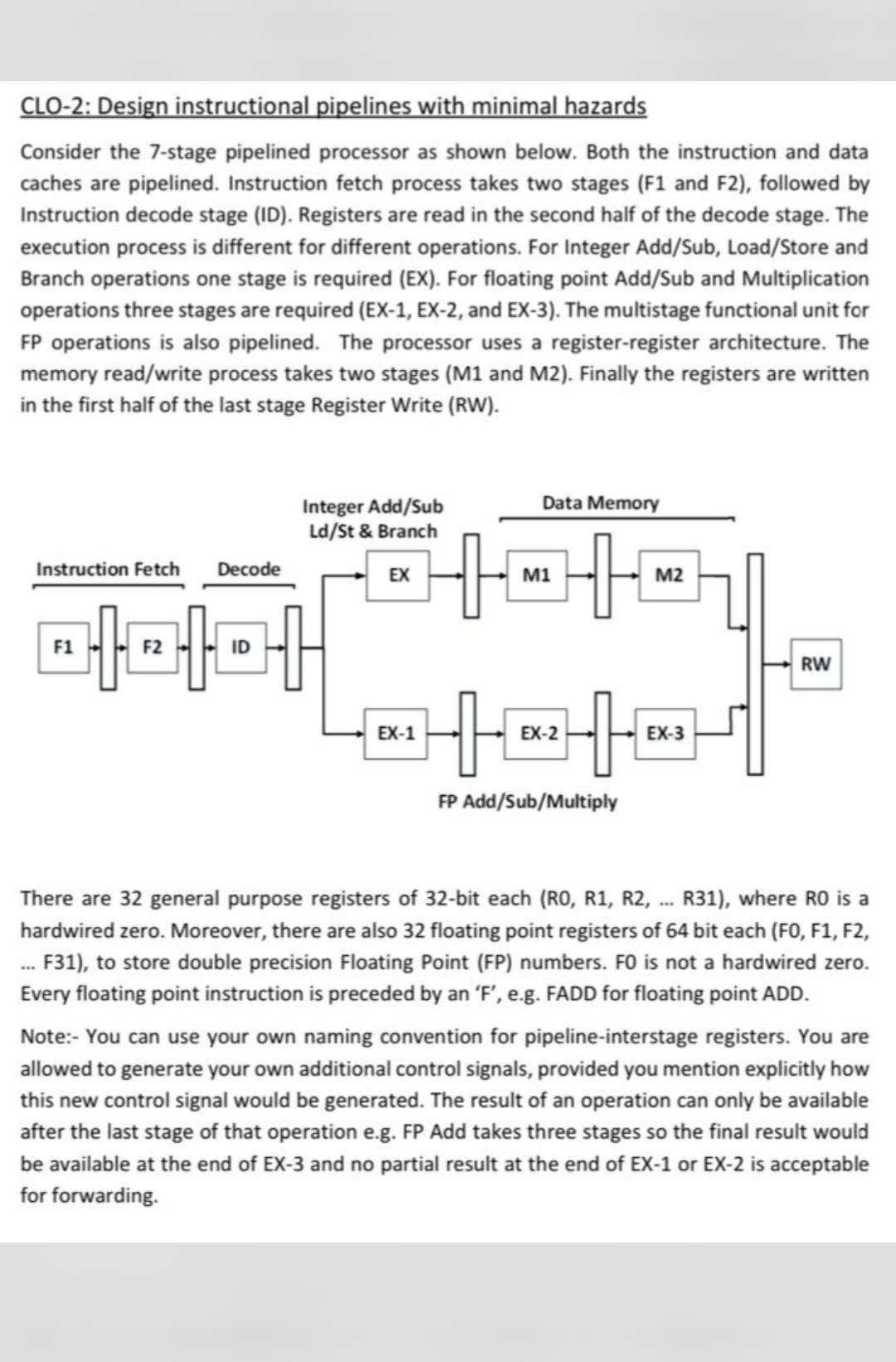
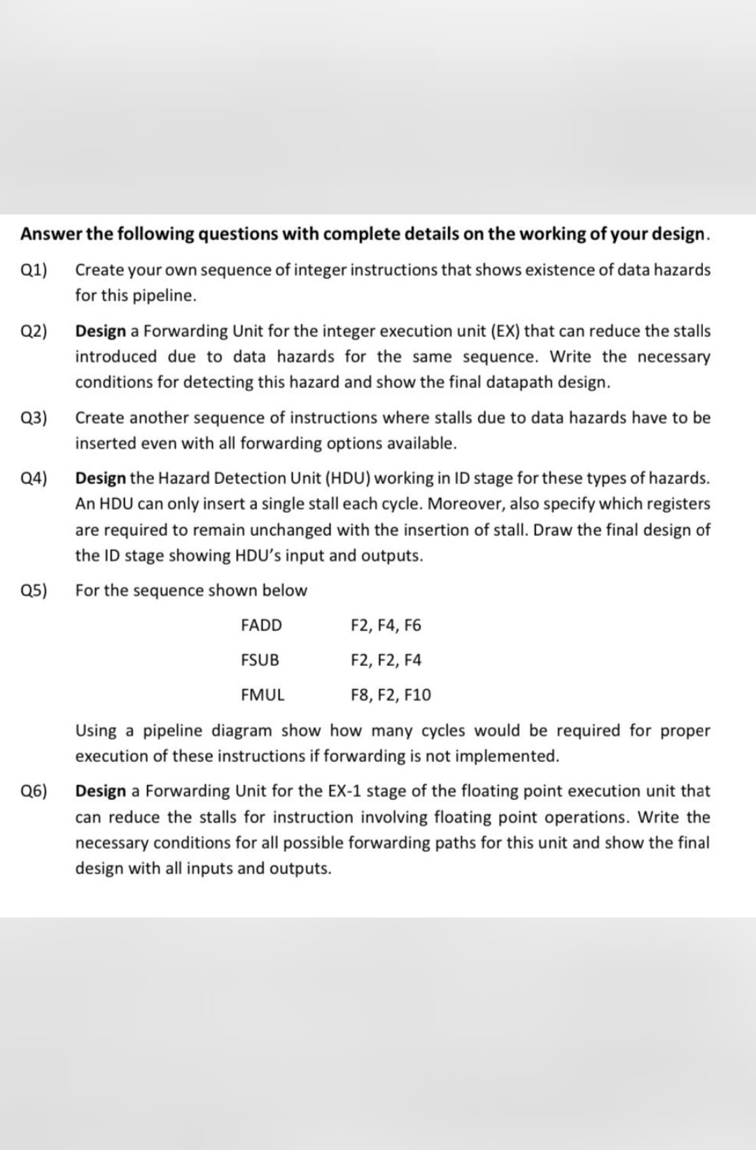
CLO-2: Design instructional pipelines with minimal hazards Consider the 7-stage pipelined processor as shown below. Both the instruction and data caches are pipelined. Instruction fetch process takes two stages (F1 and F2), followed by Instruction decode stage (ID). Registers are read in the second half of the decode stage. The execution process is different for different operations. For Integer Add/Sub, Load/Store and Branch operations one stage is required (EX). For floating point Add/Sub and Multiplication operations three stages are required (EX-1, EX-2, and EX-3). The multistage functional unit for FP operations is also pipelined. The processor uses a register-register architecture. The memory read/write process takes two stages (M1 and M2). Finally the registers are written in the first half of the last stage Register Write (RW). Data Memory Integer Add/Sub Ld/St & Branch EX Instruction Fetch Decode M1 M2 --- -1-101 ----- F1 RW FP Add/Sub/Multiply There are 32 general purpose registers of 32-bit each (RO, R1, R2, ... R31), where RO is a hardwired zero. Moreover, there are also 32 floating point registers of 64 bit each (FO, F1, F2, ... F F31), to store double precision Floating Point (FP) numbers. FO is not a hardwired zero. Every floating point instruction is preceded by an 'F', e.g. FADD for floating point ADD. Note:- You can use your own naming convention for pipeline-interstage registers. You are allowed to generate your own additional control signals, provided you mention explicitly how this new control signal would be generated. The result of an operation can only be available after the last stage of that operation e.g. FP Add takes three stages so the final result would be available at the end of EX-3 and no partial result at the end of EX-1 or EX-2 is acceptable for forwarding. a Answer the following questions with complete details on the working of your design. Q1) Create your own sequence of integer instructions that shows existence of data hazards for this pipeline. Q2) Design a Forwarding Unit for the integer execution unit (EX) that can reduce the stalls introduced due to data hazards for the same sequence. Write the necessary conditions for detecting this hazard and show the final datapath design. Q3) Create another sequence of instructions where stalls due to data hazards have to be inserted even with all forwarding options available. Q4) Design the Hazard Detection Unit (HDU) working in ID stage for these types of hazards. An HDU can only insert a single stall each cycle. Moreover, also specify which registers are required to remain unchanged with the insertion of stall. Draw the final design of the ID stage showing HDU's input and outputs. For the sequence shown below Q5) FADD F2, F4, F6 FSUB F2, F2, F4 FMUL F8, F2, F10 a Using a pipeline diagram show how many cycles would be required for proper execution of these instructions if forwarding is not implemented. Q6) Design a Forwarding Unit for the EX-1 stage of the floating point execution unit that can reduce the stalls for instruction involving floating point operations. Write the necessary conditions for all possible forwarding paths for this unit and show the final design with all inputs and outputs
Step by Step Solution
There are 3 Steps involved in it

Get step-by-step solutions from verified subject matter experts