

Question: answer question 3 a-f 12V Figure 1-3 3. Answer the following questions based on Figure 1-3 (30-pt.). a). In the half-wave rectification circuit shown in
answer question 3 a-f
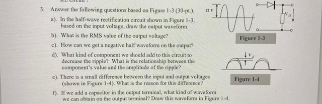
12V Figure 1-3 3. Answer the following questions based on Figure 1-3 (30-pt.). a). In the half-wave rectification circuit shown in Figure 1-3, based on the input voltage, draw the output waveform. b). What is the RMS value of the output voltage? c). How can we get a negative half waveform on the output? d). What kind of component we should add to this circuit to decrease the ripple? What is the relationship between the component's value and the amplitude of the ripple? e). There is a small difference between the input and output voltages (shown in Figure 1-4). What is the reason for this difference? f). If we add a capacitor in the output terminal, what kind of waveform we can obtain on the output terminal? Draw this waveform in Figure 1-4. Figure 1-4
Step by Step Solution
There are 3 Steps involved in it

Get step-by-step solutions from verified subject matter experts