

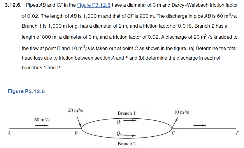
Question: Applied Hydraulics # 3 . 1 2 . 6 . Pipes A B and C F in the Figure P 3 . 1 2 .
Applied Hydraulics #
Pipes and in the Figure have a diameter of and DarcyWeisbach friction factor of The length of is and that of is The discharge in pipe is Branch is long, has a diameter of and a friction factor of Branch has a length of a diameter of and a friction factor of A discharge of is added to the flow at point and is taken out at point as shown in the figure. a Determine the total head loss due to friction between section A and and b determine the discharge in each of branches and
Step by Step Solution
There are 3 Steps involved in it
1 Expert Approved Answer
Step: 1 Unlock

Question Has Been Solved by an Expert!
Get step-by-step solutions from verified subject matter experts
Step: 2 Unlock
Step: 3 Unlock