

Question: As illustrated in the figure below, the ( mathrm { O } - 2 ) wing is modeled as a beam with
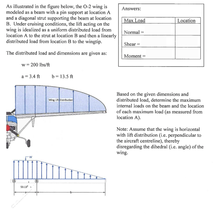
As illustrated in the figure below, the mathrmO wing is modeled as a beam with a pin support at location A and a diagonal strut supporting the beam at location B Under cruising conditions, the lift acting on the wing is idealized as a uniform distributed load from location A to the strut at location B and then a linearly distributed load from location B to the wingtip.
The distributed load and dimensions are given as:
beginarrayl
mathrmwmathrmlbsmathrmft
mathrmamathrmftquad mathrm~bmathrmft
endarray
Answers:
Based on the given dimensions and distributed load, determine the maximum internal loads on the beam and the location of each maximum load as measured from location A
Note: Assume that the wing is horizontal with lift distribution ie perpendicular to the aircraft centreline thereby disregarding the dihedral ie angle of the wing.
Step by Step Solution
There are 3 Steps involved in it
1 Expert Approved Answer
Step: 1 Unlock

Question Has Been Solved by an Expert!
Get step-by-step solutions from verified subject matter experts
Step: 2 Unlock
Step: 3 Unlock