

As shown in Figure 1, one portion of the hot flue gases is supplied to the steam
Question:
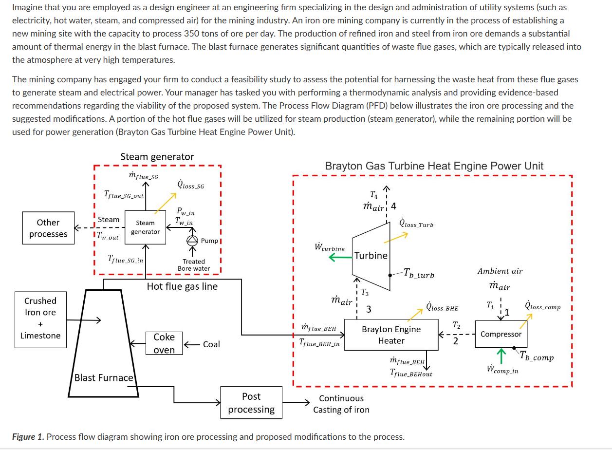
As shown in Figure 1, one portion of the hot flue gases is supplied to the steam generator. The steam generator is a shell and tube type of heat exchanger. In this steam generator treated bore water flows through the tubes while the hot flue gases flow in the shell, and steam is produced. The average demand of the steam for other processes within the iron/steel industry is 250 kg/hr at 154 ℃ temperature and 400kPa absolute pressure. Treated bore water is supplied to the steam generator at an average temperature of 20℃. The average pressure drop in the water line of the steam generator is 10kPa. The flue gases enter the shell and tube heat exchanger (steam generator) at a pressure of 110 kPa (Absolute) and a temperature of 251 ℃ and average mass flow rate of 129 kg/min. The average pressure drop in the flue gas side of the steam generator is 5kPa. Flue gases can be assumed to behave as ideal gas and have constant specific heat capacities equal to that of air (Cp=1.005kJ/kg.K and Cv = 0.718kJ/kg.K). The steam generator is insulated, but it still loses on average 5.8 kW of thermal energy to the surroundings though the outer surface. The outer surface of the steam generator has an average temperature of 55.3 ℃.
Brayton Gas Turbine Heat Engine Power Unit: As shown in Figure 1, remaining portion of hot flue gases is supplied the Brayton Engine Heater. In this heat engine air is used as the working fluid and air is assumed to behave as an ideal gas with constant specific heat capacities of Cp=1.005kJ/kg.K and Cv=0.718kJ/kg.K. The hot flue gases can also be assumed to behave as ideal gas and have constant specific heat capacities equal that of air (Cp=1.005kJ/kg.K and Cv = 0.718kJ/kg.K). Thermal energy for operation of the heat engine is provided by the hot flue gases.
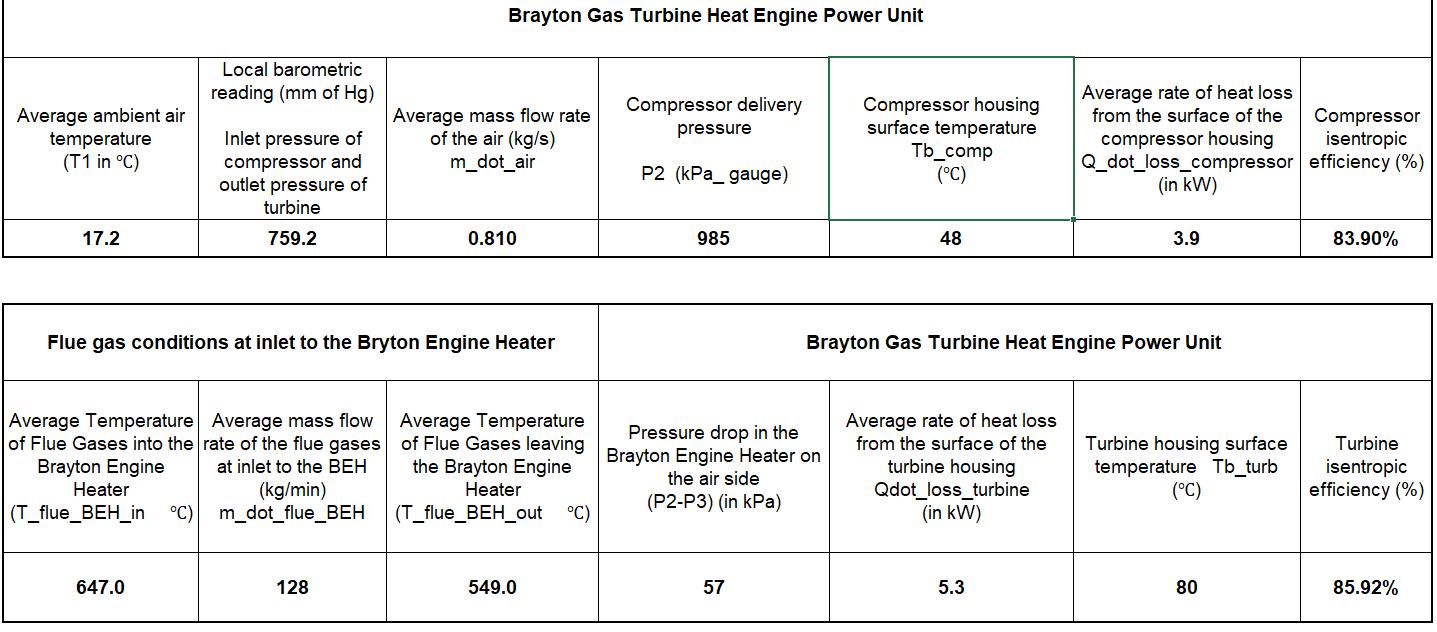
The attached spreadsheet provides the boundary conditions of the Brayton Gas Turbine Heat Engine Power Unit
Following information is provided in the spreadsheet,
Local barometric reading, average ambient air temperature, average mass flow rate of the air, compressor delivery pressure P2 (in gauge), compressor housing surface temperature, average rate of heat loss from the surface of the compressor housing, compressor isentropic efficiency, average mass flow rate and temperature in and out flue gases supplied to the Brayton Engine Heater (BEH), air side pressure drop in the BEH (i.e. P2 – P3), average rate of heat loss from the surface of the turbine housing, turbine housing surface temperature and turbine isentropic efficiency. BEH can be assumed to be very well insulated with not heat loss to the surroundings.
The ambient air at local atmospheric pressure (value provided in the spreadsheet) is compressed by the compressor at a constant mass flow rate. The compressed air is heated in the BEH as shown in the Figure 1. The rate of heat addition can be estimated from the flue gas mass flow and its temperature difference across the BEH (temperature values provided in the spreadsheet). The air experiences pressure drop as it flows through the heater due to fluid friction, the value of the pressure drop is provided in the spreadsheet. The hot compressed air is expanded in a gas turbine to the local atmospheric pressure (Point 4, given in the spreadsheet).
Assume air to behave as an ideal gas and assume constant specific heat capacity of air, cp_air = 1.005kJ/kg.K, cv_air = 0.718 kJ/kg.K, R_air = 0.287kJ/kg.K. Assume the density of mercury as 13,500kg/m3 and gravity as 9.81m/s2. Hot flue gases can also be assumed to behave as an ideal gas and have constant specific heat capacities equal that of air (Cp=1.005kJ/kg.K and Cv=0.718kJ/kg.K).
To help with the analysis follow the steps below,
Steam generator:
1. Determine the rate of entropy generation in the steam generator, in kW/K. Show all steps of the calculations, including estimating all parameters required to determine the rate of entropy generation.
Brayton Gas Turbine Heat Engine Power Unit:
2. Determine the temperatures at T2s, T2a, T3, T4s and T4a (in ℃).
3. Determine the net rate of work generation (in kW) and thermal efficiency of the Brayton gas turbine heat engine power unit (in %).
4. Determine the rate of entropy generation in the compressor and turbine separately (in kW/K).
5. To improve the performance of the power plant, it is proposed that the BEH be redesigned to reduce the pressure drop on air side to half of the original pressure drop between point 2 and 3. Using the new reduced pressure drop determine the new net power output (in kW) and the new thermal efficiency of the power plant (in %).
Expert Answer:


Principles of heat transfer
ISBN: 978-0495667704
7th Edition
Authors: Frank Kreith, Raj M. Manglik, Mark S. Bohn
