

Question: As shown in the figure below, a screw is driven by a screw driver onto a suspended rod. The rod is firmly held at one
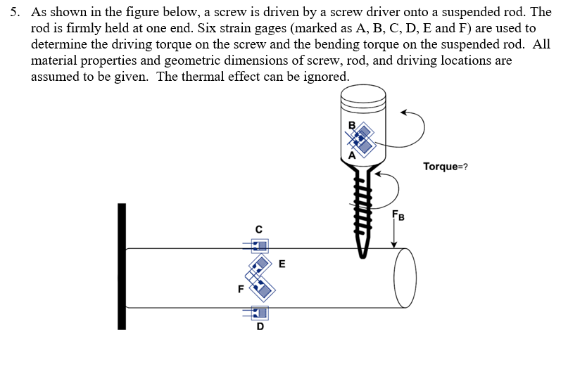
As shown in the figure below, a screw is driven by a screw driver onto a suspended rod. The
rod is firmly held at one end. Six strain gages marked as A B C D E and F are used to
determine the driving torque on the screw and the bending torque on the suspended rod. All
material properties and geometric dimensions of screw, rod, and driving locations are
assumed to be given. The thermal effect can be ignored.
Express the relationship of the measurement from each strain gage to the principal strains of torsion on the screw and bending on the rod;
Suggest the combinations of strain gage connections to the fullarm Whetstone Bridge that can be used to determine the torsional torque and bending torque. Check the corresponding bridge constants to validate the suggested combination. You may also use dummy staingages in your combination design.
Derive a formula to calculate the calibration number of torsional torque in your design.
Step by Step Solution
There are 3 Steps involved in it
1 Expert Approved Answer
Step: 1 Unlock

Question Has Been Solved by an Expert!
Get step-by-step solutions from verified subject matter experts
Step: 2 Unlock
Step: 3 Unlock