

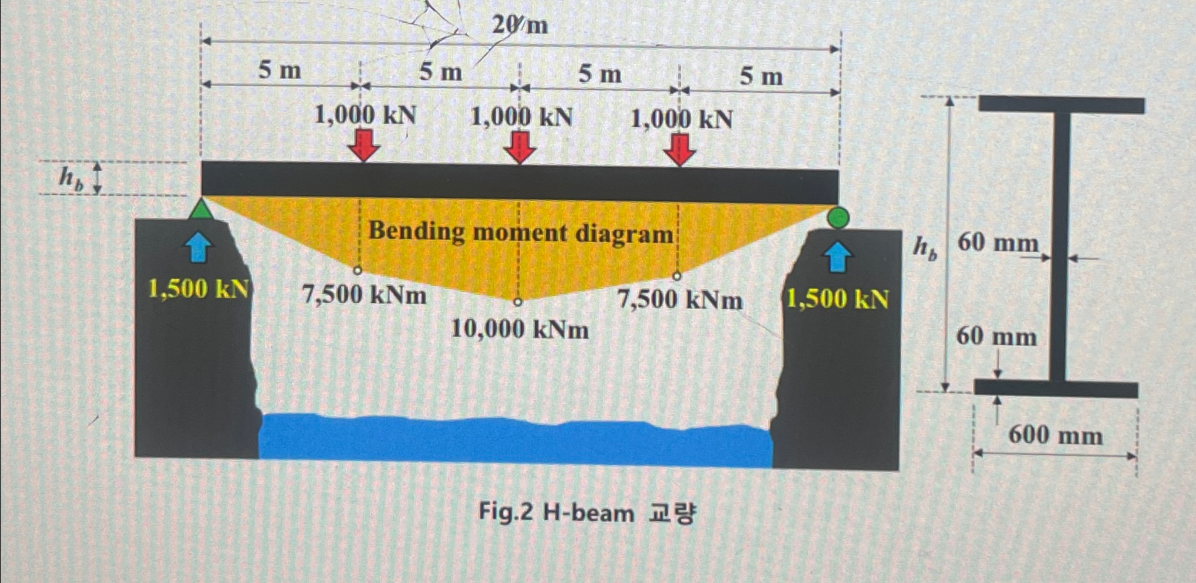
Question: As shown in the figure, we will use a simple beam structure using H - beam. From the left point A ( x = 0
As shown in the figure, we will use a simple beam structure using Hbeam. From the left point A x in the horizontal direction x and m a force of kN is applied in the vertical downward direction. For the distribution of bending moment caused by external force, refer to the figure If the width of the Hbeam crosssection is bmm and the plate thickness is tmm and the depth is h express the crosssectional secondary moment lb as a formula for hBased on the bending moment distribution diagram provided in Figure, find the distribution diagram by position in the horizontal direction of the maximum axial stress acting on the tensile edge of the cross section of hbeam It is intended to be designed so that the maximum axial stress of the tensile node is Mpa or less. Find the required depth hb and crosssectional area Ab of the hbeam crosssection When the depth of all cross sections is unified to the required depth obtained above ie using a pristine beam calculate the total volume of term materials volume Vb required for the construction of hbeam bridges.Fig. Hbeam
Step by Step Solution
There are 3 Steps involved in it
1 Expert Approved Answer
Step: 1 Unlock

Question Has Been Solved by an Expert!
Get step-by-step solutions from verified subject matter experts
Step: 2 Unlock
Step: 3 Unlock