

Question: Assignment No . 1 - Sept. 2 0 t h , 2 0 2 4 Notes: 2 0 marks will be allocated for the completion
Assignment No Sept.
Notes:
marks will be allocated for the completion of the entire assignment.
Assignment is due on the specified date at : PM through online submission.
Over the past few years, the City of Thunder Bay has developed a Master Plan to modernize
its waterfront area. This has made this area of great interest for real estate investments. As
a result, a major real estate investor is planning to construct Northern Ontario's first six
storey mass timber office building in Prince Arthur's landing zone of the City of Thunder
Bay's waterfront area. Such tall wooden buildings are now permitted under the current
building codes of several Canadian provinces, including Ontario.
A schematic of this new mass timber office building, which shall, by its shape and design,
represent a unique landmark in the Northern Ontario region on the beautiful Lake Superior,
is shown in Fig. The structural skeleton of this new building is composed of new
engineeredwood construction products. In particular, the structural framing system shall
be made of gluedlaminated timber glulam sections, while all floors shall be made of
crosslaminated timber CLT slabs supported on the glulam structural framing system.
The midrise mass timber office building shall be designed to have one highceiling
mm large lobby area with one main entrance and one set of double elevators. The elevation
difference shall be kept at mm for the repeated floors. Two staircases located at two
opposite corners of the building must be considered in the design to ensure safe and
effective evacuation of occupants in case of emergency.
Figs. through show the structural floor plans for all floors in order from bottom to top.
Fig. Schematic of the sixstorey mass timber office building skeleton.
Fig. Structural floor plan floors
Fig. Structural floor plan floors
Fig. Structural floor plan floors
Table lists all dimensions and element spacings, while Table below lists all design
load intensities.
Table Structure dimensions and element spacings
Table Load intensities
For the design of the different structural elements of this building, consider the following
general conditions, unless mentioned otherwise.
Dry service conditions.
Wood material is free of incision andor strengthreducing or fireretardant
chemicals.
Always select the most economical sections for the design of all members and show
all calculation details and steps.
Any missing information can be reasonably assumed according to rational
engineering judgment; however, any taken assumptions must be clearly stated.
Problem
marks
A canopy made of mass timber cantilevered truss systems is required to cover the top
terrace space of the building. Perform the necessary structural analysis for one of the
intermediate truss systems of this canopy using the most critical load combination as per
the WDM for the specified load intensities ie D L and S Assume each cantilevered
truss system is pinned at its top and bottom connections with the building exterior column
of the top floor. Show all loading calculations that you used as input for your structural
analysis. You can either use a structural analysis method, such as the section method andor
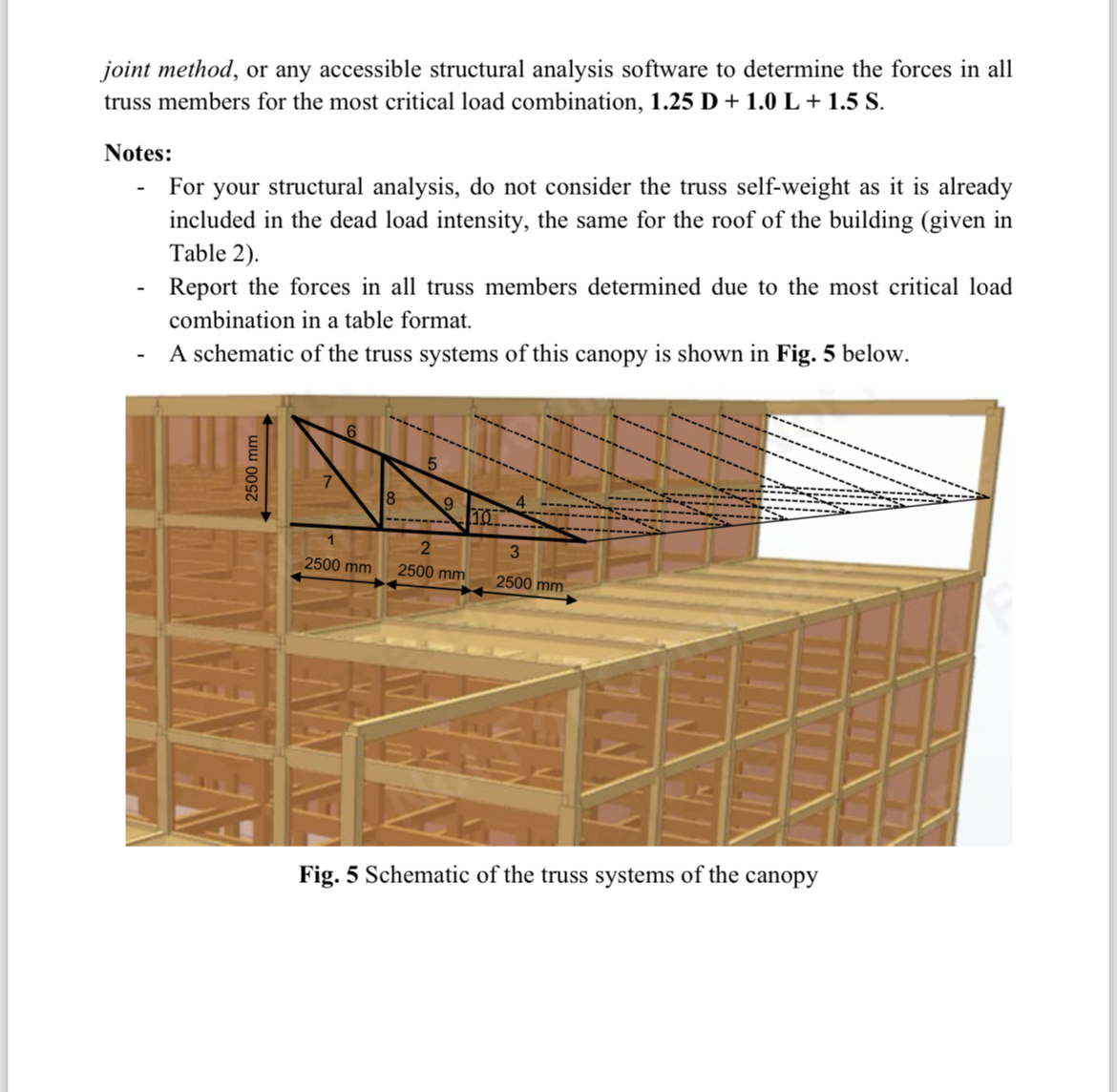
joint method, or any accessible structural analysis software to determine the forces in all truss members for the most critical load combination,
Notes:
For your structural analysis, do not consider the truss selfweight as it is already included in the dead load intensity, the same for the roof of the building given in Table
Report the forces in all truss members determined due to the most critical load combination in a table format.
A schematic of the truss systems of this canopy is shown in Fig. below.
Fig. Schematic of the truss systems of the canopy
Problem
marks
Design all members of an intermediate truss system of the canopy based on the forces
obtained from the structural analysis performed using the most critical load combination.
Use SprucePine cE for glulam sections subjected to compression and SprucePine
tE for glulam sections subjected to tension. Consider all truss members are pinned at
their ends and are connected with a single row of diameter shear plates SH PL
with diameter bolts.
Problem
marks
Design one of the intermediate columns with the largest tributary area the marked column
in Fig. at the top floor, considering the most critical design load combination. Consider
this column to be effectively pinned at both ends. Also, no eccentricity is considered. Use
SprucePine cE glulam section.
Problem
marks
Design one of the intermediate columns with the largest tributary area the marked column
in Fig. on the ground floor, considering the most critical design load com
Step by Step Solution
There are 3 Steps involved in it
1 Expert Approved Answer
Step: 1 Unlock

Question Has Been Solved by an Expert!
Get step-by-step solutions from verified subject matter experts
Step: 2 Unlock
Step: 3 Unlock