

Question: At the same site that was analyzed in the previous design project, the DOT needs to extend the highway easement 1 0 feet into the
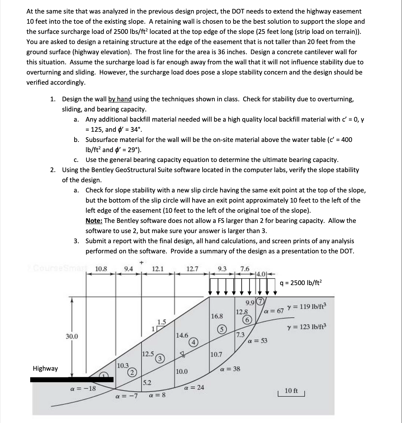
At the same site that was analyzed in the previous design project, the DOT needs to extend the highway easement feet into the toe of the existing slope. A retaining wall is chosen to be the best solution to support the slope and the surface surcharge load of mathrmlbsmathrmft located at the top edge of the slope feet long strip load on terrain You are asked to design a retaining structure at the edge of the easement that is not taller than feet from the ground surface highway elevation The frost line for the area is inches. Design a concrete cantilever wall for this situation. Assume the surcharge load is far enough away from the wall that it will not influence stability due to overturning and sliding. However, the surcharge load does pose a slope stability concern and the design should be verified accordingly.
Design the wall by hand using the techniques shown in class. Check for stability due to overturning, sliding, and bearing capacity.
a Any additional backfill material needed will be a high quality local backfill material with cprimevarphi and phiprimecirc
b Subsurface material for the wall will be the onsite material above the water table cprimemathrmlbmathrmft and phiprimecirc
c Use the general bearing capacity equation to determine the ultimate bearing capacity.
Using the Bentley GeoStructural Suite software located in the computer labs, verify the slope stability of the design.
a Check for slope stability with a new slip circle having the same exit point at the top of the slope, but the bottom of the slip circle will have an exit point approximately feet to the left of the left edge of the easement feet to the left of the original toe of the slope
Note: The Bentley software does not allow a FS larger than for bearing capacity. Allow the software to use but make sure your answer is larger than
Submit a report with the final design, all hand calculations, and screen prints of any analysis performed on the software. Provide a summary of the design as a presentation to the DOT.
Step by Step Solution
There are 3 Steps involved in it
1 Expert Approved Answer
Step: 1 Unlock

Question Has Been Solved by an Expert!
Get step-by-step solutions from verified subject matter experts
Step: 2 Unlock
Step: 3 Unlock