

Question: ATE: ON / 1 B / 2 0 2 A CE 5 3 7 . TIMBER AND MASONRY DESIGN ( 4 UNITS ) BLEM #
ATE: ONBA
CE TIMBER AND MASONRY DESIGN UNITS
BLEM #
MIDTERM EXAM # I DATE:
ren:
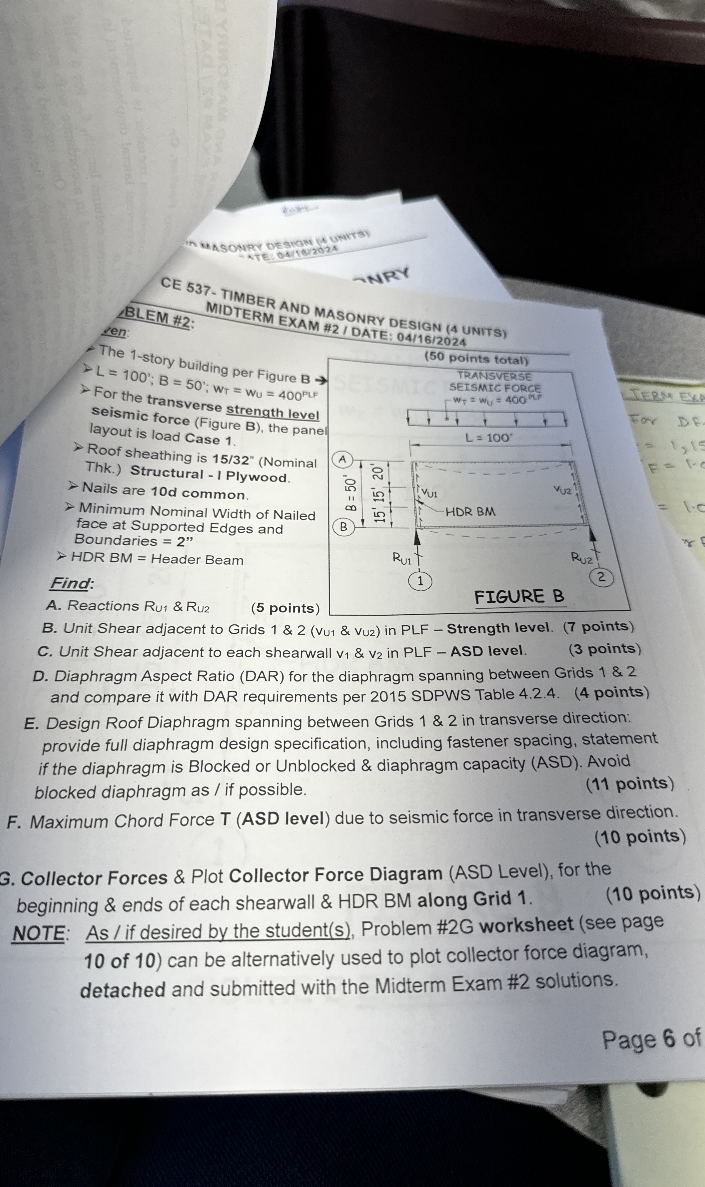
The story building per Figure
;;
For the transverse strength level
seismic force Figure B the pan:
layout is load Case
Roof sheathing is Nominal
Thk Structural I Plywood.
Nails are common.
Minimum Nominal Width of Nailed
face at Supported Edges and
Boundaries
HDR BM Header Beam
Find:
A Reactions &
points
B Unit Shear adjacent to Grids && in PLF Strength level. points
C Unit Shear adjacent to each shearwall & in PLF ASD level. points
D Diaphragm Aspect Ratio DAR for the diaphragm spanning between Grids & and compare it with DAR requirements per SDPWS Table points
E Design Roof Diaphragm spanning between Grids & in transverse direction: provide full diaphragm design specification, including fastener spacing, statement if the diaphragm is Blocked or Unblocked & diaphragm capacity ASD Avoid blocked diaphragm as if possible. points
F Maximum Chord Force T ASD level due to seismic force in transverse direction. points
G Collector Forces & Plot Collector Force Diagram ASD Level for the beginning & ends of each shearwall & HDR BM along Grid
NOTE: As if desired by the students Problem #G worksheet see page of can be alternatively used to plot collector force diagram, detached and submitted with the Midterm Exam # solutions.
Page of
Step by Step Solution
There are 3 Steps involved in it
1 Expert Approved Answer
Step: 1 Unlock

Question Has Been Solved by an Expert!
Get step-by-step solutions from verified subject matter experts
Step: 2 Unlock
Step: 3 Unlock